Plate loop thermosiphon equal temperature plate

A technology of vapor chamber and plate type, which is applied in the direction of cooling/ventilation/heating transformation, electrical components, electrical equipment construction parts, etc. The heat dissipation of the device and other issues can be achieved, and the effect of good heat transfer capacity, simple structure and flexible layout can be achieved.

Active Publication Date: 2018-06-08
SHANGHAI JIAO TONG UNIV
View PDF11 Cites 0 Cited by
  • Summary
  • Abstract
  • Description
  • Claims
  • Application Information

AI Technical Summary

Problems solved by technology

However, traditional thermosiphons are not suitable for heat dissipation of electronic devices due to structural limitations.
[0004] In traditional thermosiphons, the gaseous working medium and the liquid working medium move in opposite directions. On the one hand, the carrying limit of the working medium is limited; Its limit power affects the heat transfer efficiency
[0005] Due to the miniaturization of electronic components, reducing the size of the heat pipe has become an inevitable development trend, and the reduction of the diameter of the heat pipe will inevitably lead to an increase in the flow resistance of the working medium in the tube, and the traditional thermosiphon is mostly a circular tube structure. However, most electronic devices are flat, and the circular tube structure is not conducive to the close combination of heat pipes and electronic heat dissipation parts, which will lead to an increase in contact thermal resistance and affect heat transfer efficiency.

Method used


Image

  • Plate loop thermosiphon equal temperature plate
  • Plate loop thermosiphon equal temperature plate
  • Plate loop thermosiphon equal temperature plate

Examples


Embodiment 1

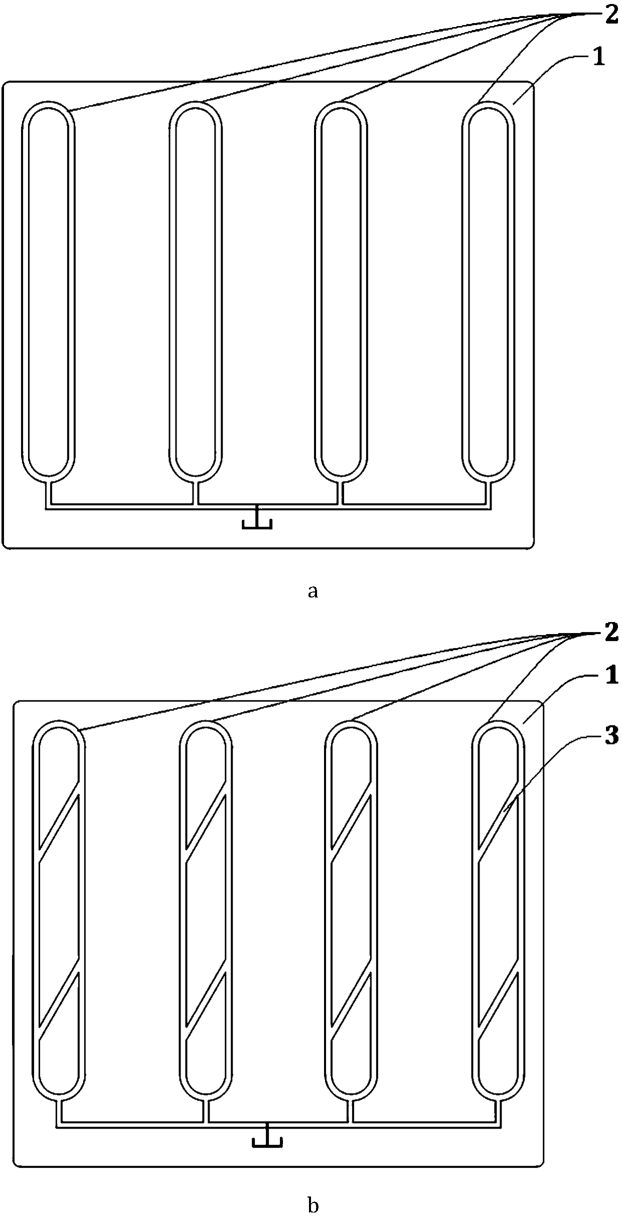
[0033] Such as figure 1 As shown in a, as the basic implementation of the present invention, this embodiment includes four ring grooves 2 arranged in parallel in the flat plate body 1, the bottoms of the ring grooves 2 are connected to each other, and the ring grooves 2 include: parallel The left main channel 21, the right main channel 22, the upper curved channel 23 and the lower curved channel 24 connecting the left main channel 21 and the right main channel 22 are provided.

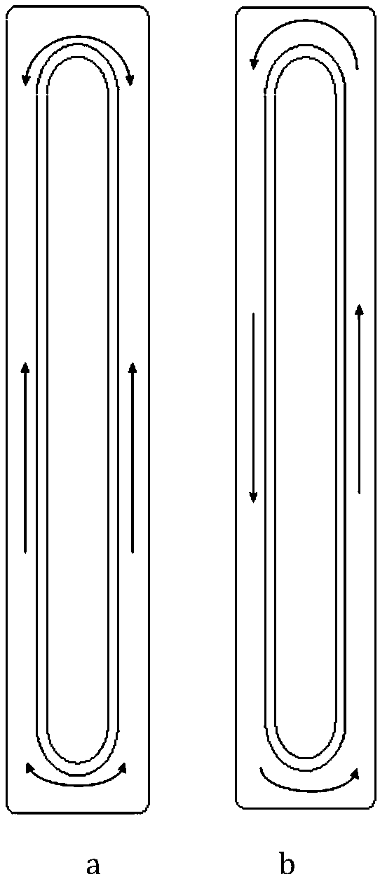
[0034] Such as figure 2 a and figure 2 As shown in b, it is a schematic diagram of the cycle in the basic realization mode of the device, where: a is a typical low-power flow mode, and b is a high-power flow mode.

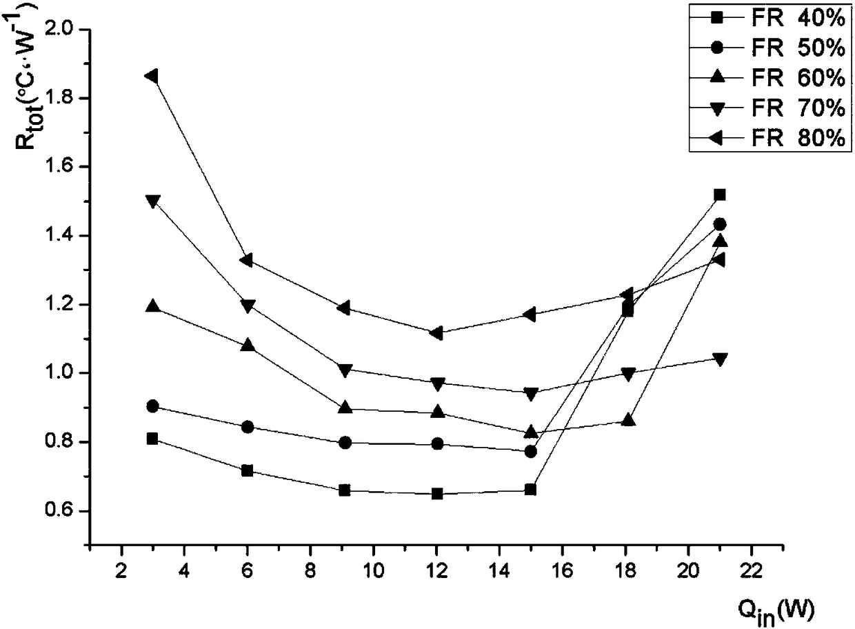
[0035] Such as image 3 As shown, it is a general diagram of the heat transfer performance of the liquid filling rate from 40% to 80% in this embodiment.

Embodiment 2

[0037] Such as figure 1 As shown in b, compared with the embodiment 1, the communication channel 3 arranged obliquely is connected between the left main channel 21 and the right main channel 22 in this embodiment, and the inclination angle is 30°-60°.

[0038] Described communication channel 3 comprises: the first chute 31 and the second chute 32 that are arranged in parallel, wherein: the second chute 32 is positioned at the evaporation section 1, and the bottom of the second chute 32 is far from the bottom of the ring groove The distance is less than 1 / 2 of the height of the evaporation section I, preferably 1 / 4 to 1 / 3 of the height of the evaporation section I; the first chute 31 is located in the condensation section II, and the distance between the bottom of the first chute 31 and the top of the ring groove The distance is 1 / 2 of the height of condensation section II.

[0039] Preferably, the condensation section II is provided with a cooling fin structure.

[0040] The...


PUM


Abstract

The invention discloses a board type loop thermosyphon uniform-temperature board, and belongs to the heat dissipation technical field of an electronic device. The board type loop thermosyphon uniform-temperature board comprises annular grooves formed in a flat board body, wherein the annular grooves comprise left and right main channels and upper and lower bending channels connected with the left and main channels; and connecting channels arranged in a tilted manner are connected between the left and right main channels. By adoption of the board type loop thermosyphon uniform-temperature board, the dimension of a heat pipe can be reduced to be matched with an electronic device; the miniaturization is realized while the contact thermal resistance is lowered, and the two-phase flowing in the heat pipe is reinforced, so that the heat exchange efficiency of the electronic device is improved consequently.

Description

technical field [0001] The invention relates to a technology in the field of heat dissipation of electronic devices, in particular to a plate-type loop thermosyphon equalization plate. Background technique [0002] With the development of electronic technology, the number, power, and density of electronic components in various electrical appliances such as notebooks, smart phones, high-power LED modules, micro projectors, and laser generators have increased rapidly, resulting in increasing thermal power consumption. At the same time, the increase of heat flux increases the surface temperature of electronic components, thus affecting the stability and service life of electrical appliances. In order to achieve effective heat dissipation of electronic equipment, many improvement measures have been proposed in the industry for the type, structure and material of heat dissipation devices, but the effect is not very satisfactory. [0003] The traditional thermosiphon is a tubular...

Claims


Application Information

Patent Timeline
Patent Type & Authority Patents(China)
IPC IPC(8): H05K7/20
CPCH05K7/20336
Inventor 洪芳军周春鹏胡伟男
Owner SHANGHAI JIAO TONG UNIV
Why Eureka
Try Eureka