Optical reflection sensor and electronic device
A light reflection and sensor technology, applied in the direction of instruments, using re-radiation, re-radiation of electromagnetic waves, etc., can solve problems such as complex structures, achieve the effect of improving detection accuracy and preventing false detection
- Summary
- Abstract
- Description
- Claims
- Application Information
AI Technical Summary
Problems solved by technology
Method used
Image

Examples
no. 1 Embodiment approach
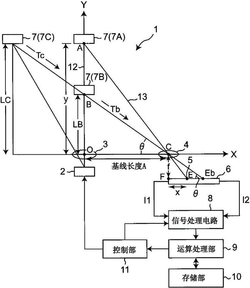
[0066] figure 1 It is a schematic diagram showing the structure of the light reflective sensor of this embodiment. The light reflective sensor of the present embodiment has a configuration in which both the above-mentioned triangulation distance measuring method and the above-mentioned TOF method are combined. exist figure 1 Among them, the light reflective sensor 1 includes: a light-emitting element 2 composed of the above-mentioned LED that irradiates light to a distance-measuring object (hereinafter simply referred to as object) 7 as an object of distance measurement; A light emitting lens 3; a light receiving lens 4 that condenses the reflected light from the object 7; In addition, other elements such as an infrared light emitting element or a laser diode may be used as the light emitting element 2 .
[0067] Assuming that the position of the above-mentioned light-emitting lens 3 is the origin O, the irradiation position of the light from the light-emitting element 2 ...
no. 2 Embodiment approach
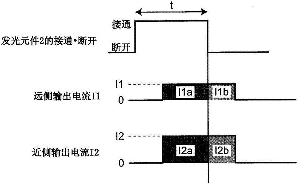
[0089] This embodiment relates to: a method of obtaining the position of the light spot 5 on the light receiving element 6 by using the above-mentioned signal processing circuit 8; The method of flight time T.
[0090] figure 2 Shown in order from the top: the timing of turning on (on) and off (off) of the above-mentioned driving signal output from the above-mentioned control unit 11 to the light-emitting element 2 (that is, turning on and off of the light-emitting element 2 ); a change in the far-side output current as a detection signal on the far side of the element 6 ; and a change in the near-side output current as a detection signal on the near side of the light receiving element 6 .
[0091] Here, the far side of the light receiving element 6 refers to the side where the reflected light from the distant object 7 forms the light spot 5 in the light receiving element 6 which is a PSD. In addition, the near side of the light receiving element 6 refers to the side where ...
no. 3 Embodiment approach
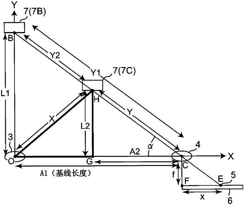
[0100] This embodiment relates to obtaining the deviation from the base line to the position on the optical axis of the light-emitting element 2 when the light emission angle of the light-emitting element 2 is expanded without using the time-of-flight lookup table of the first embodiment. The method of the distance of the object 7 of the position.
[0101] In this embodiment, if image 3 As shown, assume a case where an object 7C to be measured is located at an intermediate position between the light-emitting lens 3 and the light-receiving lens 4 .
[0102] The above-mentioned signal processing circuit 8 first obtains the position of the light spot 5 on the light-receiving element 6 based on the far-side output current I1 and the near-side output current I2 from the light-receiving element 6 as a PSD, for example, through the processing of the above-mentioned second embodiment. , measure the length (distance x) of side FE of triangle FCE. Furthermore, using the arithmetic pr...
PUM
 Abstract
Description
Claims
Application Information
 - R&D
- Intellectual Property
- Life Sciences
- Materials
- Tech Scout
- Unparalleled Data Quality
- Higher Quality Content
- 60% Fewer Hallucinations
Browse by: Latest US Patents, China's latest patents, Technical Efficacy Thesaurus, Application Domain, Technology Topic, Popular Technical Reports.
© 2025 PatSnap. All rights reserved.Legal|Privacy policy|Modern Slavery Act Transparency Statement|Sitemap|About US| Contact US: help@patsnap.com