Smoke purification and heat exchange integration device
A flue gas purification and heat storage technology, which is applied in waste heat treatment, climate sustainability, lighting and heating equipment, etc., can solve the problems of thermal shock damage of filter elements, reduce the service life of filter elements, energy loss, etc., and achieve guaranteed Effects of stabilization, damage reduction, and improvement of waste heat recovery rate
- Summary
- Abstract
- Description
- Claims
- Application Information
AI Technical Summary
Problems solved by technology
Method used
Image
Examples
Embodiment 1
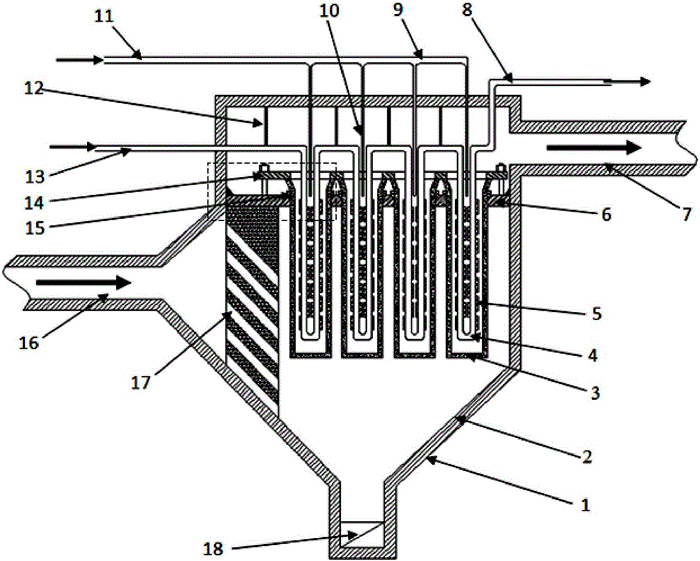
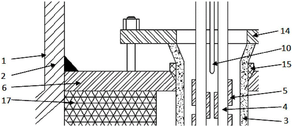
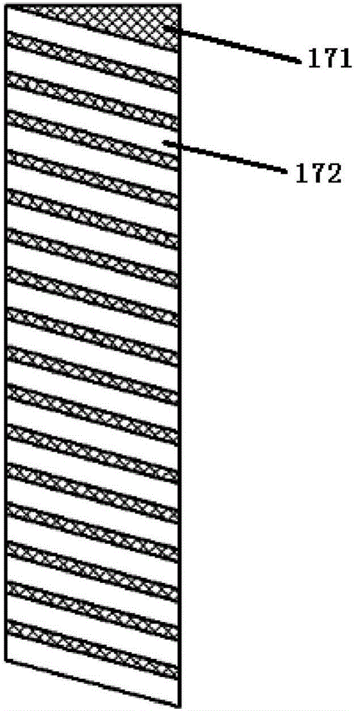
[0035] This preferred embodiment discloses an integrated device for flue gas purification and heat exchange. Such as figure 1 and figure 2 As shown, the flue gas purification and heat exchange integrated device includes a shell 1, a thermal insulation layer 2 attached to the inner wall of the shell 1, a flower plate 6 that divides the shell 1 into a dust collection chamber and a clean air chamber, and an insert The ceramic filter membrane tube 3 connected to the flower plate 6, the heat exchange tube 4 placed in the ceramic filter membrane tube 3, the cover plate 14 covered above the opening of the ceramic filter membrane tube 3, the heat exchange tube 4 for fixing The fixed frame 12, the ash unloading valve 18 at the bottom of the housing 1, the thermal storage wall 17 for storing or releasing heat for the flue gas, and the blowback ash cleaning assembly.
[0036] The part above the flower plate 6 is a clean air chamber, and the part below is a dust collecting chamber. Bo...
Embodiment 2
[0050] This preferred embodiment discloses an integrated device for flue gas purification and heat exchange, which is basically the same as the device described in the first preferred embodiment, including a shell, a flower plate that divides the shell into a dust collection chamber and a clean air chamber , the ceramic filter membrane tube inserted on the flower plate, the heat exchange tube placed in the ceramic filter membrane tube, and the heat storage wall used to store or release heat for the flue gas. The smoke outlet is connected to the smoke outlet, the smoke inlet is connected to the dust collection chamber, and the smoke outlet is connected to the clean air chamber; the heat storage wall is located in the dust collection chamber near the smoke inlet.
[0051] The difference is that: if Figure 5 and Figure 6 As shown, although the flue gas passage 172 is inclined downward along the thickness direction of the heat storage body 171 and arranged at intervals, the cro...
Embodiment 3
[0053] This preferred embodiment discloses an integrated device for flue gas purification and heat exchange, which is basically the same as the device described in preferred embodiment 1 or 2, except that: Figure 7 and Figure 8 As shown, although the flue gas passage 172 is inclined downward along the thickness direction of the heat storage body 171 and arranged at intervals, the cross section of the flue gas passage 172 is zigzag, and the zigzag flue gas passage 172 can increase the amount of heat between the flue gas and the heat storage material. The contact area improves the heat storage and heat release efficiency. The cross section of the flue gas channel 172 includes but is not limited to several shapes in the embodiments, and can also be other shapes, which can be set according to actual use requirements.
PUM
 Abstract
Description
Claims
Application Information
 - R&D
- Intellectual Property
- Life Sciences
- Materials
- Tech Scout
- Unparalleled Data Quality
- Higher Quality Content
- 60% Fewer Hallucinations
Browse by: Latest US Patents, China's latest patents, Technical Efficacy Thesaurus, Application Domain, Technology Topic, Popular Technical Reports.
© 2025 PatSnap. All rights reserved.Legal|Privacy policy|Modern Slavery Act Transparency Statement|Sitemap|About US| Contact US: help@patsnap.com


