Multifunctional vacuum furnace

A vacuum furnace, multi-functional technology, applied in furnaces, muffle furnaces, cooking furnaces, etc., can solve the problems of long heating and holding time, single cooling gas running direction, inconsistent workpiece temperature, etc., to achieve high product performance and heat preservation And the effect of short cooling time and uniform cooling

Inactive Publication Date: 2017-03-15
SHENYANG HENGJIN VACUUM TECH
View PDF6 Cites 13 Cited by
  • Summary
  • Abstract
  • Description
  • Claims
  • Application Information

AI Technical Summary

Problems solved by technology

[0002] With the shortage of energy and the improvement of environmental protection emission standards, the requirements for energy-saving and environmental protection vacuum equipment are getting higher and higher. At present, domestic vacuum equipment used in sintering, heat treatment, such as annealing, tempering, brazing and other processes has high energy consumption. , low production efficiency, the workpiece needs to be heated for a long time or increase the heating temperature

Method used


Image

  • Multifunctional vacuum furnace
  • Multifunctional vacuum furnace
  • Multifunctional vacuum furnace

Examples


Example Embodiment

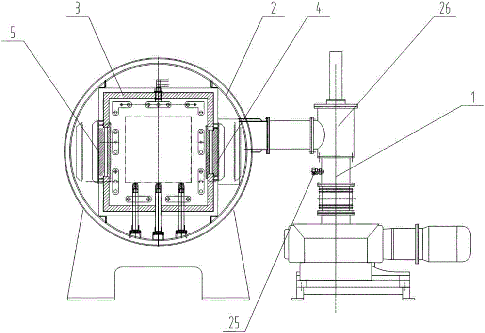
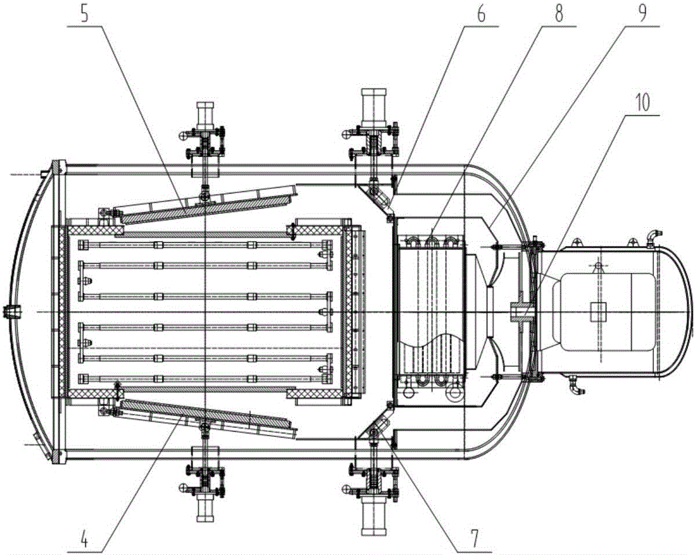
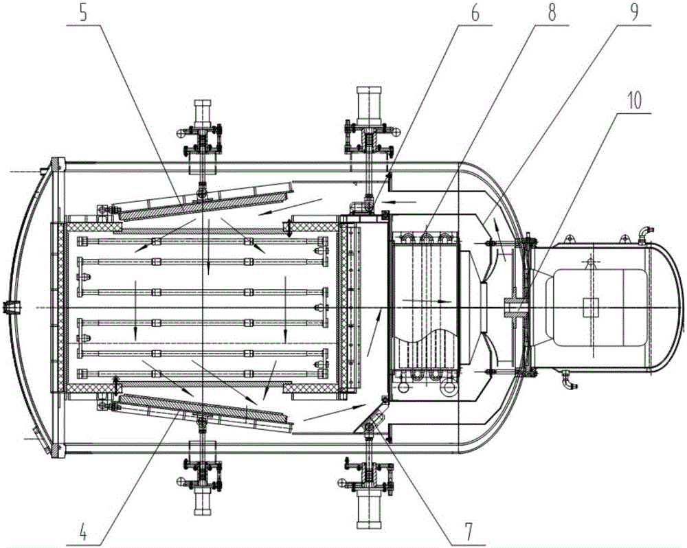
[0018] The multifunctional vacuum furnace of the present invention includes furnace shell, heating chamber, vacuum system, cooling system, PLC intelligent control system, see figure 1 , 2 The furnace shell 2 is a cylindrical vacuum-tight container, installed axially parallel to the ground, the front end of the cylinder is a spherical door, and the rear of the furnace shell 2 is a cooling system, including a fan 10, a heat exchanger 8, and an air duct 9. A vacuum system 1 is installed on the outside of the furnace shell 2 and connected by a valve 26. A square heating chamber 3 is arranged axially in the furnace shell 2. It is characterized in that the vertical walls of the heating chamber 3 are equipped with a front right air door 4 and a front left air door 5 that move left and right. Front right and front left air doors 4 and 5 are connected to the vertical wall of the heating chamber 3 by the front vertical sides of the frame bodies. Inside the furnace shell 2, at the rear of ...


PUM


Abstract

Disclosed is a multifunctional vacuum furnace. The multifunctional vacuum furnace is characterized in that the front portion of the body of a heating chamber is provided with a movable front left air door and a movable front right air door, a rear left reversing air door and a rear right reversing air door are symmetrically installed at the air flue end outside the heating chamber, air door air cylinders are installed outside a furnace shell, and air cylinder piston rods penetrate through the furnace shell to be connected with air door pin shafts through sealing structures. The multifunctional vacuum furnace has the advantages that in the heating process, the front left air door and the front right air door are closed, no air through hole is formed, energy loss in the heating process is avoided, energy is saved, and it is ensured that heating is more uniform; and in the cooling process, the opening degree of the front left air door and that of the front right air door are large, meanwhile, the rear left air door and the rear right air door can achieve reversing, in other words, airflow alternately flows in a reversing mode inside the heating chamber, outside the heating chamber, on the left of the heating chamber and on the right of the heating chamber, reversing time can be set, accordingly, workpieces are uniformly cooled, the cooling speed is increased, and the furnace discharge time is shortened. The problem that production efficiency is affected is solved, energy consumption is lowered to minimum, product performance is higher, and production efficiency is improved.

Description

technical field [0001] The invention relates to vacuum equipment in sintering and heat treatment processes, and is an energy-saving and environment-friendly multifunctional vacuum furnace. Background technique [0002] With the shortage of energy and the improvement of environmental protection emission standards, the requirements for energy-saving and environmental protection vacuum equipment are getting higher and higher. At present, domestic vacuum equipment used in sintering, heat treatment, such as annealing, tempering, brazing and other processes has high energy consumption. , low production efficiency, the workpiece needs to be heated for a long time or increase the heating temperature to achieve temperature consistency, and the cooling gas running direction is single. Problems: if the cooling gas enters from the nozzles around the heating chamber and flows out from the front and rear end screens of the shell, or The cooling gas enters from the front and exits from the...

Claims


Application Information

Patent Timeline
IPC IPC(8): F27B5/05
CPCF27B5/04
Inventor 高光伟杨建川曲绍芬石岩赵建业刘舒于德军
Owner SHENYANG HENGJIN VACUUM TECH
Why Eureka
Try Eureka