An optical fiber-based atomic force microscope probe and atomic force microscope system

An atomic force microscope and optical fiber technology, applied in scanning probe microscopy, scanning probe technology, instruments, etc., can solve the problems of complex measurement system, material temperature drift error stress, complex structure, etc., and achieve high measurement accuracy and sensitivity , Simplify the difficulty of using the system and expand the scope of use

Active Publication Date: 2019-08-06
SHANDONG UNIV
View PDF3 Cites 1 Cited by
  • Summary
  • Abstract
  • Description
  • Claims
  • Application Information

AI Technical Summary

Problems solved by technology

[0009] The light reflection detection method has the advantages of high sensitivity and high detection accuracy, but the measurement system based on the current cantilever beam probe structure is relatively complex, uses a large number of optical devices, and is complicated to operate and bulky, which is not conducive to system simplification and miniaturization. Limiting its use in biological detection and micro-measurement environments, the shortcomings of current cantilever beam probe measurements are:
[0010] (1) The system needs to be calibrated before testing, and the operation is complicated:
[0011] The cantilever beam probe and the optical signal detection part are independent structures. It is necessary to adjust the relative position of the micro-cantilever beam and each optical collimation device to ensure the transmission of the optical circuit. The relative position of each device needs to be precisely calibrated to ensure the measurement accuracy of the system. Difficulty of using the system;
[0012] (2) The structure is complex and bulky, which is not conducive to the miniaturization design of the system:
[0013] The optical detection system uses a variety of optical collimation devices, resulting in complex structure, high cost, and large volume of the entire system, which is not conducive to the miniaturization design of the system and limits the scope of use of the system;
[0014] (3) Not suitable for long-distance detection:
[0017] (5) The material properties of the cantilever beam probe and its supporting structure are inconsistent, or the material of the probe and the micro-cantilever beam is inconsistent, which may easily cause temperature drift errors caused by material thermal mismatch and stress problems between different materials

Method used


Image

  • An optical fiber-based atomic force microscope probe and atomic force microscope system
  • An optical fiber-based atomic force microscope probe and atomic force microscope system
  • An optical fiber-based atomic force microscope probe and atomic force microscope system

Examples


Embodiment 1

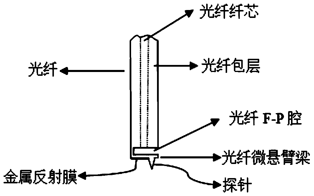
[0052] Example 1: A fiber-based atomic force microscope probe

[0053] like image 3 and Figure 7 As shown, the optical fiber-based atomic force microscope probe mainly includes a probe 5, a micro-cantilever beam 4, an optical fiber F-P cavity 5, and a light-transmitting optical fiber. The technology (dry etching, anisotropic wet etching) is integrated and processed on the tip of a 125μm diameter optical fiber. The probe 5, the micro-cantilever beam 4 and the optical fiber F-P cavity 3 are an integral structure, which can be integrally processed and formed without connecting parts. In addition, the probe 5 can also be prepared separately instead of an integrated structure, and then bonded to one end of the micro-cantilever beam through other processing techniques, which can ensure the diversity of probe structure and material selection and expand the scope of use of the system; One side of the probe is coated with a highly reflective metal film, a dielectric reflective fil...

Embodiment 2

[0061] Example 2: An atomic force microscope system based on a fiber optic atomic force microscope probe

[0062] like Image 6 As shown, an atomic force microscope system based on a fiber-optic atomic force microscope probe includes the above-mentioned fiber-based atomic force microscope probe, transmission fiber, coupler, laser light source, light intensity detection device, feedback controller and displacement scanning platform. When the probe is very close to the sample surface, a weak van der force is generated between the atoms at the tip of the probe and the atoms on the sample surface. When the light-transmitting fiber is transmitted to the top of the fiber, the interface light reflection will occur at the position of the fiber F-P cavity, and the reflected light will return to the optical signal detection device through the original path of the fiber; and the change of the length of the F-P cavity caused by the micro-cantilever microvariation will cause the reflected ...


PUM


Abstract

The invention relates to a fiber-based atomic force microscope probe and an atomic force microscope system. The fiber-based atomic force microscope probe comprises a probe pin and a micro cantilever beam; and the probe pin is arranged at one end of the micro cantilever beam arranged at one end of a fiber. A fiber F-P cavity is formed between the micro cantilever beam and one end surface of the fiber by a connecting arm. And the micro cantilever beam is used for sensing a change of a distance between the probe pin and a sample. When the length of the F-P cavity changes due to deformation of the micro cantilever beam, the reflected light intensity is modulated by the fiber F-P cavity.

Description

technical field [0001] The invention belongs to the scanning direction of sample surface topography in the fields of material science, experimental physics and biomolecules, and in particular relates to an optical fiber-based atomic force microscope probe and an atomic force microscope system. Background technique [0002] Atomic Force Microscope is an analytical instrument that can be used to study the surface structure of solid materials including insulators, biomolecules, etc. The basic principle of the atomic force microscope is: fix one end of a microcantilever that is extremely sensitive to weak force, There is a tiny probe at the other end of the micro-cantilever beam. When the distance between the micro-cantilever beam probe and the sample surface is very close, there is an extremely weak interaction force between the atoms at the probe tip and the atoms on the sample surface (10 -12 ~10 -6 N), the micro-bending deformation of the micro-cantilever will occur. The f...

Claims


Application Information

Patent Timeline
Patent Type & Authority Patents(China)
IPC IPC(8): G01Q60/40G01Q60/24G01Q70/16G01Q70/08
CPCG01Q60/24G01Q60/40G01Q70/08G01Q70/16
Inventor 曹弘毅张雷姜明顺隋青美曹玉强张法业
Owner SHANDONG UNIV
Why Eureka
Try Eureka