Light spot and powder spot automatic collaboration controlled laser metal added material manufacturing device and method

A metal additive and manufacturing device technology, which is applied in the field of laser metal additive manufacturing devices, can solve the problems such as the inability to guarantee the forming quality of variable melting width forming, and achieves a combination of efficiency and accuracy, improving forming efficiency, and ensuring forming accuracy and quality. Effect

Active Publication Date: 2017-03-22
NORTHWESTERN POLYTECHNICAL UNIV
View PDF9 Cites 27 Cited by
  • Summary
  • Abstract
  • Description
  • Claims
  • Application Information

AI Technical Summary

Problems solved by technology

However, according to the research on the interaction between laser and powder and the deposition process of simultaneous powder-feeding laser additive manufacturing, in the actual forming process, the spot size-powder spot size-other forming process parameters must have a good match to achieve a good forming effect
Only dynamically adjusting the size of the laser spot without synchronously controlling the powder delivery will not be able to guarantee the forming quality of variable width forming

Method used


Image

  • Light spot and powder spot automatic collaboration controlled laser metal added material manufacturing device and method
  • Light spot and powder spot automatic collaboration controlled laser metal added material manufacturing device and method
  • Light spot and powder spot automatic collaboration controlled laser metal added material manufacturing device and method

Examples


example 1

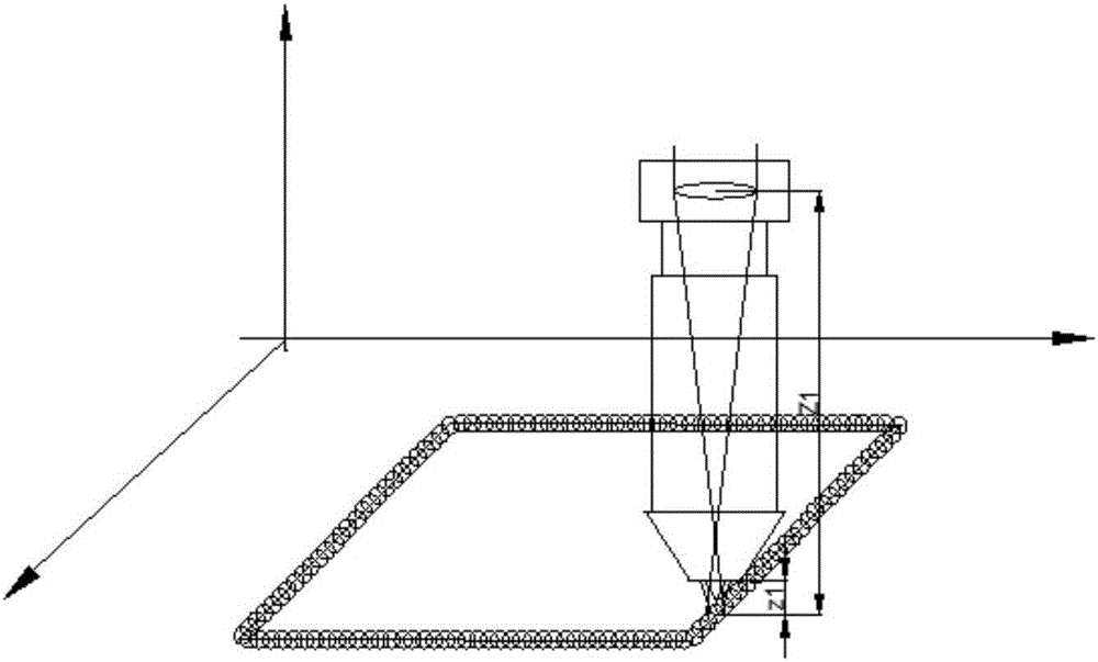
[0035] When adopting the method described in the present invention to form the member with variable wall thickness in one pass, such as figure 2 As shown, it includes the following steps.

[0036] Step 1. Obtain the correspondence between the spot size of the workpiece processing surface and the distance Z from the focusing mirror to the workpiece processing surface, and the relationship between the powder spot size and the distance z from the powder feeding nozzle to the workpiece processing surface through experimental measurement and optical geometry calculation. Correspondence;

[0037] Step 2, through the process experiment and the measurement of the geometric dimensions of the cladding layer, establish a process database including the correspondence between the three data of cladding layer size, spot size and powder spot size, and establish the cladding layer size based on the data of the process database Controllable spot and powder spot synergistic control strategy; ...

example 2

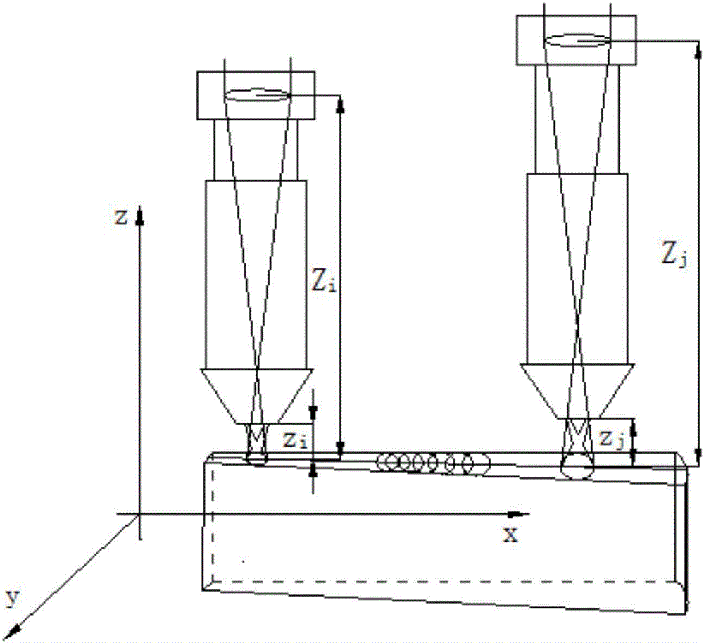
[0044] Using the method of the present invention to improve the forming efficiency and precision of laser additive manufacturing when forming thick and large components, such as Figure 4 As shown, it specifically includes the following steps:

[0045] Step 1. Obtain the correspondence between the spot size of the workpiece processing surface and the distance Z from the focusing mirror to the workpiece processing surface, and the relationship between the powder spot size and the distance z from the powder feeding nozzle to the workpiece processing surface through experimental measurement and optical geometry calculation. Correspondence;

[0046] Step 2, through the process experiment and the measurement of the geometric dimensions of the cladding layer, establish a process database including the correspondence between the three data of cladding layer size, spot size and powder spot size, and establish the cladding layer size based on the data of the process database Controlla...


PUM


Abstract

The invention discloses a light spot and powder spot automatic collaboration controlled laser metal added material manufacturing device and a method. The device comprises a connecting joint, a laser focusing head and a sleeve respectively fixed at the upper end and the lower end of the connecting joint, a mobile sleeve slidingly coating the sleeve, a powder feeding nozzle fixed at the lower end of the mobile sleeve, and a numerical control worktable for placing workpieces; the laser focusing head is used for forming light spots on workpiece machined surfaces of a focusing mirror; the powder feeding nozzle is used for gathering powder currents to feed in a machining position to form powder spots on the workpiece machined surfaces; the centers of the light spots and the powder spots are overlapped always; the numerical control worktable is used for driving the workpieces to perform the space movement corresponding to the focusing mirror to control the out-of-focus distance; and a driving device is arranged on the mobile sleeve for driving the powder feeding nozzle to move up and down through the mobile sleeve to control the sizes of the powder spots. When the method forms thick and large workpieces with the cladding layer sizes exceeding the adjusting range, the profile scanning and filling scanning combined path formation is adopted.

Description

technical field [0001] The invention relates to a laser metal additive manufacturing method for synchronous powder feeding, in particular to a laser metal additive manufacturing device and method for automatically cooperating and controllable light spots and powder spots. Background technique [0002] Synchronous powder feeding laser metal additive manufacturing technology, as an emerging technology field in the manufacturing industry, has developed rapidly in recent years. The principle is to first generate the 3D CAD solid model of the part in the computer, and then slice the model layered according to a certain thickness, convert the 3D shape data information of the part into a series of 2D plane profile information, and then under the control of the numerical control system, The method of synchronous powder feeding laser cladding is used to fill the given two-dimensional shape point by point on a certain substrate with metal materials according to a certain filling path,...

Claims


Application Information

Patent Timeline
Patent Type & Authority Applications(China)
IPC IPC(8): B22F3/105B33Y10/00B33Y30/00
CPCB22F3/003B33Y10/00B33Y30/00B22F10/00B22F10/36B22F12/70B22F10/25B22F10/366B22F10/322B22F12/53Y02P10/25
Inventor 谭华王耿林鑫杨海欧黄卫东
Owner NORTHWESTERN POLYTECHNICAL UNIV
Why Eureka
Try Eureka