
A Grinding Mechanism for Erhu Tuddle Automatic Processing Machine

A technology of automatic processing and grinding, which is applied to the parts of grinding machine tools, machine tools designed for grinding the rotating surface of workpieces, and multi-purpose machines. It can solve the problems of high processing cost, high labor intensity and low processing efficiency. Achieve the effect of reliable grinding action, low labor intensity and high precision

Active Publication Date: 2018-11-09
SUZHOU INST OF INDAL TECH
View PDF5 Cites 0 Cited by
  • Summary
  • Abstract
  • Description
  • Claims
  • Application Information

AI Technical Summary

Problems solved by technology

[0002] The existing erhu peg processing is basically a single-process manual operation, such as peg grinding, punching and cutting. These processes cannot be indexed, and must be completed manually one by one.
[0003] Especially for the grinding process of the erhu peg, since there is no special grinding mechanism on the market for grinding the peripheral surface of the erhu peg, it is basically completed by half-machine and half-manual.
This backward grinding method of the peripheral surface of the peg shaft not only requires a large number of operators, but also has high labor intensity and high processing cost, and it is difficult to guarantee the grinding quality of the peripheral surface of the peg shaft, the processing consistency is poor, it is easy to scrap, and the processing efficiency is low.
In addition, a large amount of wood chips will be produced in the grinding process. If these wood chips are scattered in the workshop for a long time, it will not only pollute the environment, but also cause harm to the health of the workers.

Method used


Image

  • A Grinding Mechanism for Erhu Tuddle Automatic Processing Machine
  • A Grinding Mechanism for Erhu Tuddle Automatic Processing Machine
  • A Grinding Mechanism for Erhu Tuddle Automatic Processing Machine

Examples


Embodiment Construction

[0029] The present invention will be described in detail below with reference to the accompanying drawings and in combination with embodiments.

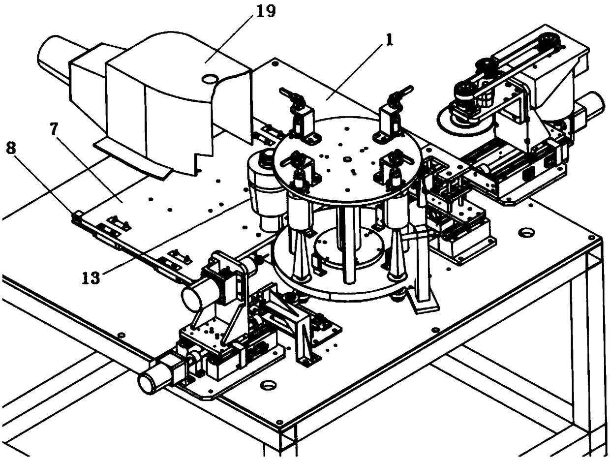
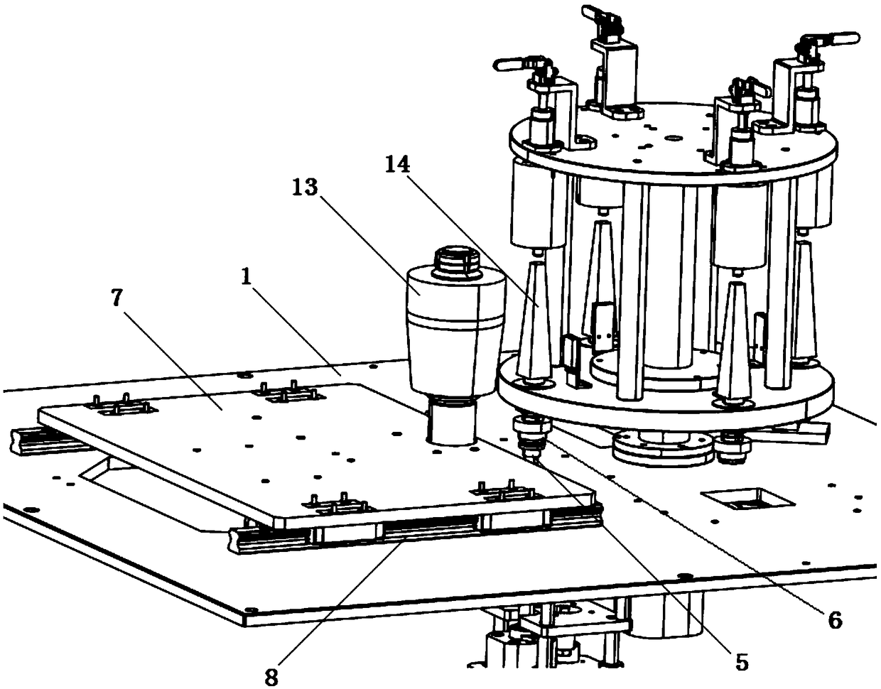
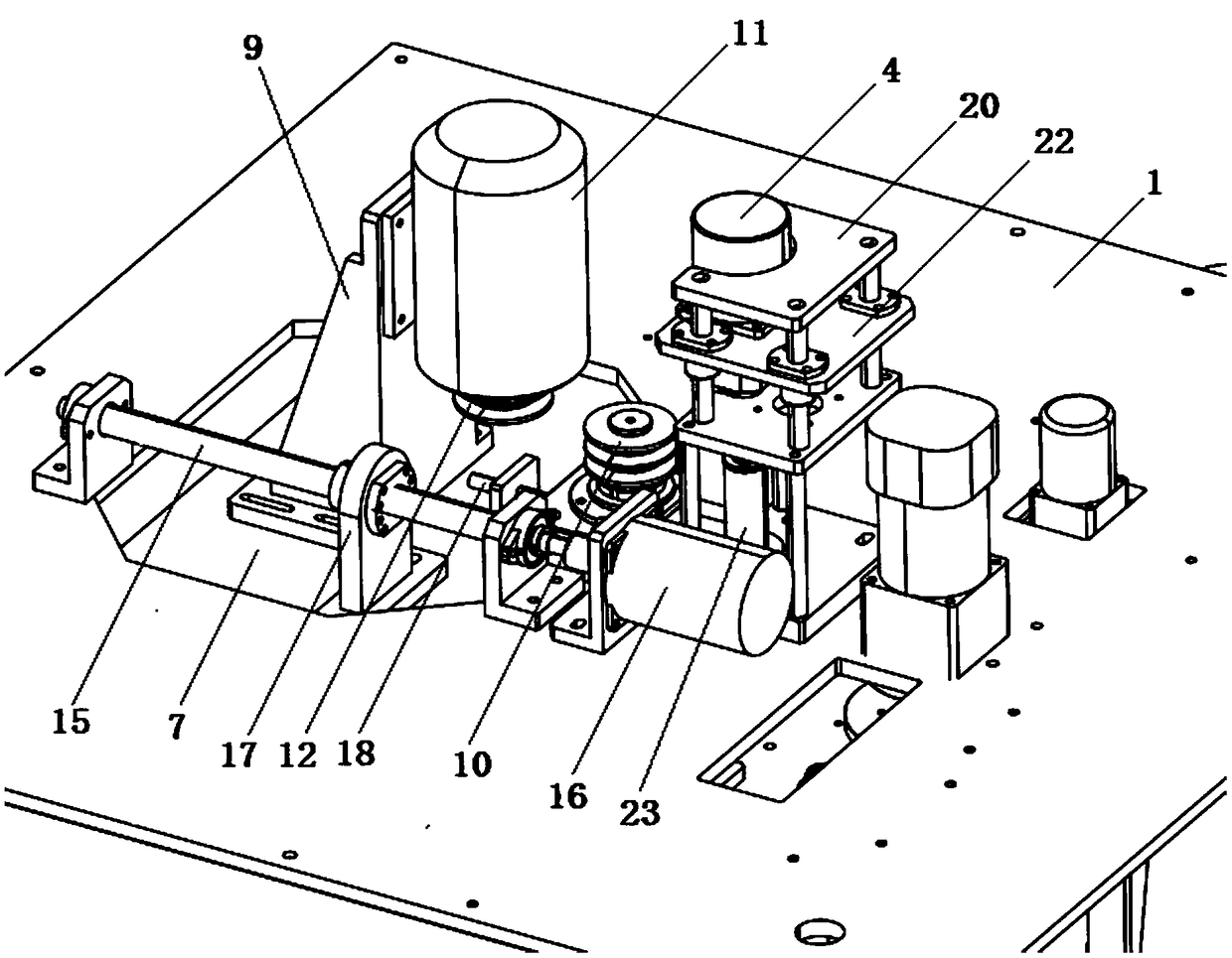
[0030] refer to Figure 1-3 As shown, a grinding mechanism for an erhu peg automatic processing machine is composed of a grinding device and a coupling device arranged on the processing table 1;

[0031] The coupling device includes a connecting rod 2 vertically arranged on the processing table 1, the upper part of the connecting rod 2 is located above the processing table 1, and the lower part of the connecting rod 2 is located on the processing table. Below the table top 1; the bottom end of the connecting rod 2 is connected with a peg blank rotation driving motor 4 for driving the connecting rod 2 to rotate, and the bottom of the connecting rod 2 is connected with a motor 4 for controlling the connection The connecting shaft device that the rod 2 stretches up and down drives the cylinder 3, and the top end of the connecting rod 2...


PUM


Abstract

The invention discloses a grinding mechanism applied to an automatic processing machine of an erhu tuning peg. The grinding mechanism is composed of a grinding device and a connecting shaft device, wherein the connecting shaft device comprises a connecting rod, a tuning peg blank rotary drive motor is connected to the bottom end, a drive air cylinder of the connecting shaft device is connected to the lower part, and a driving wheel of the connecting shaft device is disposed on the top end; and the grinding device comprises a grinding device slide plate which is driven by a grinding head feeding motor, a grinding head drive motor is disposed on the lower surface of the grinding device slide plate, and the grinding head drive motor is transmitted by a belt and connected to a shaped grinding head. According to the invention, the shaped grinding head can automatically enter or leave a grinding station during grinding, and a linear displacement sensor is disposed to control a grinding size, so automatic grinding is achieved, manual operations are not needed, and labor strength is low; and grinding actions are reliable, and the circular face of the processed tuning peg has high accuracy. According to the invention, a protective cover is disposed on the shaped grinding head; an air draft device is connected to the end; and wood bits generated during the grinding can be absorbed during grinding processing, so healthy and environment-friendly effects are achieved.

Description

technical field [0001] The invention relates to a grinding mechanism controlled by PLC, which is used for grinding the peripheral surface of the peg when the erhu peg is automatically processed. Background technique [0002] The existing erhu peg processing is basically a single-process manual operation, such as the grinding, punching and cutting of the peg. These processes not only cannot be indexed, but must all be completed manually one by one. [0003] Especially the grinding process of the erhu peg, because there is not a kind of grinding mechanism specially used for grinding the peripheral surface of the erhu peg on the market, so it is basically completed by semi-mechanical and semi-manual at present. This backward grinding method of the peripheral surface of the peg shaft not only requires a large number of operators, but also has high labor intensity and high processing cost, and it is difficult to guarantee the grinding quality of the peripheral surface of the peg ...

Claims


Application Information

Patent Timeline
Patent Type & Authority Patents(China)
IPC IPC(8): B24B5/04B24B47/20B24B47/12B24B55/04B24B55/06B24B5/50B24B49/00B27C9/00
CPCB24B5/04B24B5/50B24B47/12B24B47/20B24B49/00B24B55/04B24B55/06B27C9/00
Inventor 马俊沈进顾涛刘瑞勋李力轩
Owner SUZHOU INST OF INDAL TECH
Learn More