Novel electromagnetic multi-rotor aircraft based on turbine engine and control method thereof

A multi-rotor aircraft and turbine engine technology, applied in the field of control, can solve the problems of multi-rotor aircraft control difficulties, low energy reuse rate, etc., and achieve the effects of improving energy utilization rate, rich flight attitude, and accurate control mode

Active Publication Date: 2017-03-22
NANJING UNIV OF AERONAUTICS & ASTRONAUTICS
View PDF7 Cites 2 Cited by
  • Summary
  • Abstract
  • Description
  • Claims
  • Application Information

AI Technical Summary

Problems solved by technology

[0007] Purpose of the invention: In order to overcome the deficiencies in the prior art and solve the problems of difficult control of existing multi-rotor aircraft and low or even zero energy reuse rate, a new type of electromagnetic multi-rotor aircraft based on a turbine engine and its control method have been invented.

Method used


Image

  • Novel electromagnetic multi-rotor aircraft based on turbine engine and control method thereof
  • Novel electromagnetic multi-rotor aircraft based on turbine engine and control method thereof
  • Novel electromagnetic multi-rotor aircraft based on turbine engine and control method thereof

Examples


Embodiment 1

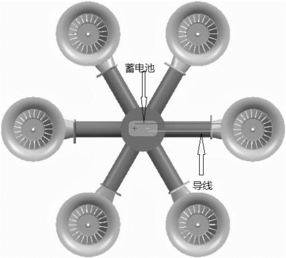
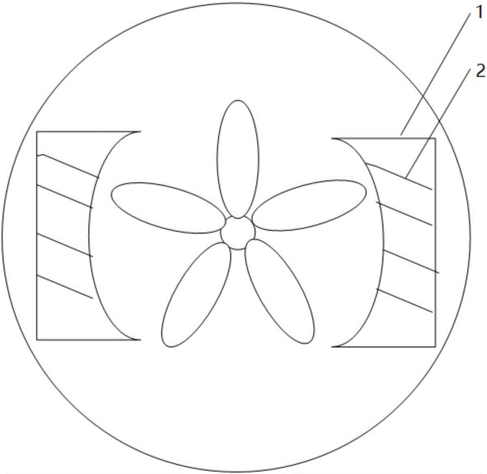
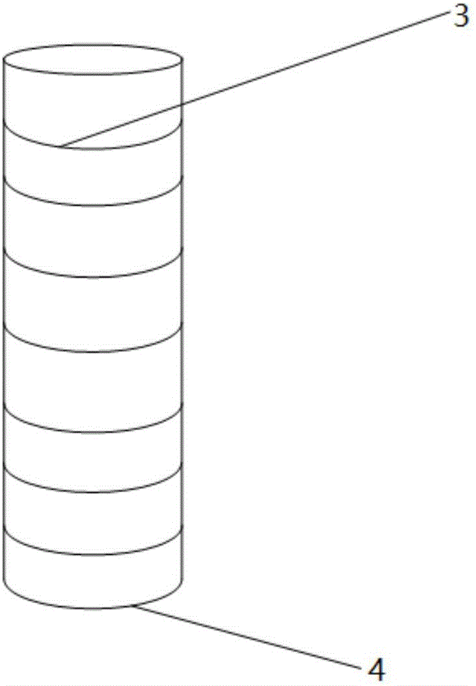
[0049] Add electromagnetic modules and batteries to turbojet engines to form a new control structure for multi-rotor aircraft, such as figure 1 . The structure diagram of ducted fan is as follows: figure 2 As shown, 1 is the magnet located around the ducted fan, and 2 is the excitation coil wound on the magnet. Wherein 3 is an induction coil, and 4 is a ducted fan (bearing) of a multi-rotor aircraft. The present invention places an induction coil 3 at the center of the ducted fan bearing 4 to generate electric current and store it through a storage battery 6 . Such as image 3 As shown, 4 of them are ducted fan (rotor) bearings, such as Figure 4 Shown, 5 is also fan bearing, and 6 is variable resistance, and 7 is central accumulator, and accumulator is installed in the ducted fan (rotor) center of multirotor aircraft. The present invention consists of multiple Figure 4 rotor assembly. The permanent magnet adopts neodymium iron angle boron with extremely high magnetic ...

Embodiment 2

[0051] When the multi-rotor aircraft decelerates, a magnetic field is formed when the excitation coil is energized, and at the same time, the ducted fan acts as an armature to rotate and cut the magnetic field lines to generate eddy currents. The eddy currents in the armature interact with the magnetic field to create a braking torque. The excitation coil and the magnet constitute the stator, and the fan acts as the rotor to cut the magnetic induction line to achieve the effect of braking.

[0052] The excitation coil is the part of the control circuit. When working, it is connected with direct current to form a magnetic field. The excitation coil is fixed on the magnetic pole and forms a whole with the magnetic pole as a stator. It will generate heat during operation, so high temperature resistant electromagnetic wire is used. A DC current is passed into the coil, so there is a magnetic flux phase link between the rotor and the stator, so that the rotor is in a closed loop of...

Embodiment 3

[0055] For the multi-rotor aircraft structure described in Scheme 1, through the variable resistance in the loop between the central battery and each rotor, the current in the ducted fan (rotor) is changed to control the rotation speed of the rotor. When a certain rotor of the aircraft needs to increase the lift, the resistance can be reduced so that the current increases to drive the rotor to have a greater rotational speed and form a greater lift. At the same time, when the attitude of the multi-rotor aircraft needs to be fine-tuned, it is only necessary to change the size of the resistance to ensure the balance of the multi-rotor flight. In addition to adjusting the attitude of the multi-rotor aircraft and fine-tuning its balance, the electric energy in the central battery can provide power for other parts of the multi-rotor aircraft.

[0056] The way to realize the flight attitude is:

[0057] 1) Descent: The airflow to all airway valves decreases, the airflow to the roto...


PUM


Abstract

The invention discloses a novel electromagnetic multi-rotor aircraft based on a turbine engine and a control method thereof. The structure of the novel multi-rotor aircraft is formed by installing induction coils, magnets surrounded closely by excitation coils and a battery on the multi-rotor aircraft. The novel multi-rotor aircraft utilizes the battery to collect induced currents to supply power for other parts of the multi-rotor aircraft to realize the energy reuse. At the same time, by means of electromagnetic eddy currents and variable resistors, the control of the multi-rotor aircraft is realized. The structure of the multi-rotor aircraft has the advantages of being easy to deploy, accurate in control mode and superior in development cost and concrete implementation, so that the novel multi-rotor aircraft has a great application prospect.

Description

technical field [0001] The invention belongs to the technical field of control, and in particular relates to a novel electromagnetic multi-rotor aircraft based on a turbine engine and a control method. Background technique [0002] With the development of science and technology, multi-rotor aircraft has gradually penetrated into our lives, and the utilization rate of the power source of multi-rotor aircraft has become an issue of increasing concern. Electromagnetic effect has been applied to daily life by a large number of scholars. Electromagnetic effect can not only generate induced current, but also form electromagnetic field. The method of using electromagnetic effect to achieve braking is mainly divided into electromagnetic powder braking, electromagnetic eddy current braking and electromagnetic friction braking. [0003] 1. Electromagnetic powder braking: When the excitation coil is energized, a magnetic field is formed, and the magnetic powder is magnetized under the...

Claims


Application Information

Patent Timeline
Patent Type & Authority Applications(China)
IPC IPC(8): B64D27/24B64D27/26B64C27/32
CPCB64C27/32B64D27/24B64D27/26B64U30/20
Inventor 赵昶袁家斌
Owner NANJING UNIV OF AERONAUTICS & ASTRONAUTICS
Why Eureka
Try Eureka