
Multi-injection staged W flame boiler using swirl pulverized coal burner

A pulverized coal burner, multiple injection technology, applied in the burner, burner, use of lump fuel and powder fuel combustion, etc. The problems such as the burner are not fully manifested, and the effect of suppressing the generation of NOx, strong rigidity, and reducing NOx is achieved

Active Publication Date: 2017-03-22
HARBIN INST OF TECH
View PDF6 Cites 19 Cited by
  • Summary
  • Abstract
  • Description
  • Claims
  • Application Information

AI Technical Summary

Problems solved by technology

However, due to the absence of overburned air, NO x Emissions are still as high as 1000mg / m 3 , and the fly ash combustible content is still at a high level
The Chinese invention patent "W Flame Boiler with Swirl Pulverized Coal Burner Primary and Secondary Air Eccentric Arrangement" was published on May 4, 2016, the application number was 201511007686.8, and the application date was December 28, 2015. The W flame was proposed The method of eccentric arrangement of the primary and secondary air pipes of the swirl burner of the boiler can reduce the NO to a certain extent by realizing partial offset of the secondary air x emissions and fly ash combustible content, to prevent slagging of the water walls on the front and rear walls of the lower furnace, but only using the swirl burner with the partial offset of the secondary air does not solve the air volume ratio between the arch and the arch, and the air volume of the arch It still accounts for more than 60% of the total air volume, and the low NO of the burner cannot be fully displayed x characteristics, NO in actual operation x Emissions up to 950mg / m 3 , fly ash combustible content up to 9%

Method used


Image

  • Multi-injection staged W flame boiler using swirl pulverized coal burner
  • Multi-injection staged W flame boiler using swirl pulverized coal burner
  • Multi-injection staged W flame boiler using swirl pulverized coal burner

Examples


specific Embodiment approach 1

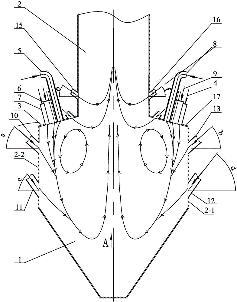
[0023] Specific implementation mode one: combine Figure 1-Figure 3 Describe this embodiment mode, a kind of multi-injection graded W flame boiler using a swirl pulverized coal burner described in this embodiment mode, it includes a lower furnace 1, an upper furnace 2, a front furnace arch 3 and a rear furnace arch 17, which It also includes N swirl pulverized coal burners with fully biased secondary air in the front furnace arch, N swirl pulverized coal burners with completely biased secondary air in the rear furnace arch, N exhaust air nozzles 10 in front, and N rear Exhaust air nozzles 13, N front grading air nozzles 11, N rear grading air nozzles 12, 2N groups of front burn-out air nozzles 15 and 2N groups of after-burning air nozzles 16; upper furnace 2, lower furnace 1, fore furnace Arch 3 and back furnace arch 17 constitute the furnace, N front furnace arch secondary air fully offset swirl pulverized coal burners are evenly distributed on the front furnace arch 3, N rea...

specific Embodiment approach 2

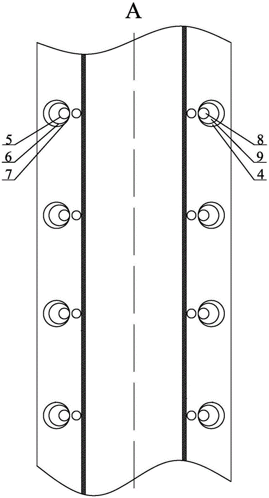
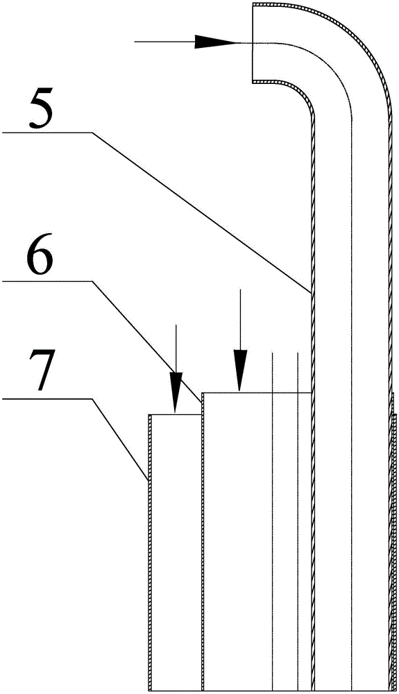
[0024] Specific implementation mode two: combination Figure 1-Figure 2 Describe this embodiment, a multi-injection graded W flame boiler using a swirl pulverized coal burner described in this embodiment, the secondary air of the front furnace arch is completely offset by the swirl pulverized coal burner including the previous air duct 5 , the front inner secondary air duct 6 and the front outer secondary air duct 7, the previous air duct 5, the front inner secondary air duct 6 and the front outer secondary air duct 7 are all vertically installed on the front furnace arch 3, the front outer The secondary air duct 7 and the front inner secondary air duct 6 are sequentially set on the previous air duct 5 from outside to inside, the outer wall of the previous air duct 5 is attached to the inner wall of the front inner secondary air duct 6, and the front inner The outer side wall of the secondary air duct 6 is attached to the inner side wall of the front outer secondary air duct 7...

specific Embodiment approach 3

[0025] Specific implementation mode three: combination figure 1 Describe this embodiment, a multi-injection graded W flame boiler using a swirl pulverized coal burner described in this embodiment, the rear furnace arch secondary air is completely biased and the swirl pulverized coal burner includes the rear primary air duct 8 , the rear inner secondary air duct 9 and the rear outer secondary air duct 4, the rear primary air duct 8, the rear inner secondary air duct 9 and the rear outer secondary air duct 4 are all vertically installed on the rear furnace arch 17, and the rear inner The secondary air duct 9 and the rear outer secondary air duct 4 are sequentially sleeved on the rear air duct 8 from outside to inside, and the outer wall of the latter air duct 8 is attached to the inner wall of the rear inner secondary air duct 9, and the rear The outer wall of the inner secondary air duct 9 is attached to the inner wall of the rear outer secondary air duct 4, the latter air duct...


PUM


Abstract

The invention discloses a multi-injection staged W flame boiler using a swirl pulverized coal burner, relates to a boiler and belongs to the technical field of W flame boiler combustion. In order to further lower the NOx emission and fly ash combustible matter content of the W flame boiler using the swirl pulverized coal burner, the W flame boiler uses the swirl pulverized coal burner with secondary air being offset completely. Secondary air pipes skew towards the side far away from the center of a hearth relative to a primary air pipe, and finally the internal secondary air pipe and the external secondary air pipe make contact with the pipe wall of the primary air pipe so that the secondary air can be offset completely; internal secondary air and external secondary air which are far away from the center of the hearth are injected step by step and carry dense pulverized coal airflow to be injected downwards, and primary and secondary staged combustion is achieved; and exhaust gas, staged air and over fire air nozzles are all arranged in a descending mode, and accordingly third, fourth, fifth and sixth staged combustion is realized. According to the W flame boiler using the swirl pulverized coal burner, multi-injection staged combustion is achieved.

Description

technical field [0001] The invention relates to a boiler, in particular to a multi-injection graded W flame boiler using a swirl pulverized coal burner. Background technique [0002] The W-flame boiler of the swirl burner in the prior art is a boiler specially designed for burning anthracite and lean coal. The following problems generally exist in the actual operation of this boiler. [0003] The upwind of W-flame boilers with swirl burners accounts for more than 60% of the total air volume, and the pulverized coal has strong oxidation at the initial stage of combustion, and NO x Emissions are high. NO x It is toxic to animals and humans, is one of the main substances that form acid rain, is also an important substance that forms photochemical smog in the atmosphere and an important factor that destroys the atmospheric ozone layer. According to the "Emission Standard of Air Pollutants for Thermal Power Plants" GB13223-2011, W Flame Boiler NO x The maximum allowable emiss...

Claims


Application Information

Patent Timeline
IPC IPC(8): F23C5/08F23C7/00F23C7/02F23D1/02
CPCF23C5/08F23C7/00F23C7/02F23C2201/20F23C2700/06F23D1/02
Inventor 陈智超王青祥李鑫张鑫张晓研曾令艳李争起
Owner HARBIN INST OF TECH
Learn More