
Integral imaging three dimensional display apparatus and method

A technology of three-dimensional display and integrated imaging, applied in optics, instruments, nonlinear optics, etc., can solve the problems of noise, unsuitable for large-scale three-dimensional display fields, etc., and achieve the effect of enhancing the depth of three-dimensional images

Active Publication Date: 2017-03-22
NANJING CEC PANDA LCD TECH
View PDF5 Cites 8 Cited by
  • Summary
  • Abstract
  • Description
  • Claims
  • Application Information

AI Technical Summary

Problems solved by technology

However, mechanical motion can cause noise and is not suitable for large-scale 3D display applications

Method used


Image

  • Integral imaging three dimensional display apparatus and method
  • Integral imaging three dimensional display apparatus and method
  • Integral imaging three dimensional display apparatus and method

Examples


Embodiment Construction

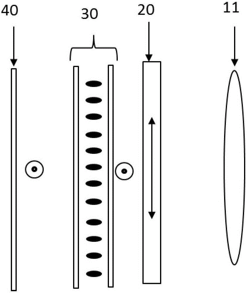
[0039] The invention relates to an integrated imaging three-dimensional display device, such as figure 2 As shown, the integrated imaging three-dimensional display device includes in sequence: a microlens array 10, a uniaxial crystal plate 20, a TN box 30, a lower polarizer 40, and a display panel 50, wherein the display panel 50 is a function of displaying images, specifically Related to TFT-LCD, OLED (Organic Light Emitting Diode), PDP (Plasma Display Panel), FED (Field Emission Display), CNT (Carbon Nanotube Display), SED (Surface Conduction Electron Emission Display); lower polarizer 40 The function is to change the outgoing light of the display panel 50 into linearly polarized light.

[0040]When the display panel 50 is a TFT liquid crystal display, and the upper polarizer is provided on the surface of the display panel 50, the polarization axis of the lower polarizer 40 is perpendicular to the polarization axis of the upper polarizer, which is usually configured in the ...


PUM


Abstract

The invention provides an integral imaging three dimensional display apparatus and method. The integral imaging three dimensional display apparatus successively includes a microlens array, a single shaft crystal slab, a TN box, a lower polaroid, a display panel, a first center depth plane and a second center depth plane, wherein when the TN box is in the open state, emergent light passes through the single shaft crystal slab; as the light emitted from an image primitive of the display panel passes through the microlens array, an image distance is formed and is lo; the first center depth plane is located at the image distance lo; when the TN box is the closed state, after the emergent linearly polarized light passes through the TN box, the polarization direction of the emergent linearly polarized light changes, and the polarization direction of the emergent linearly polarized light is parallel to the optical axis direction of the single shaft crystal slab; when the emergent light passes through the single shaft crystal slab, the light emitted from the image primitive of the display panel passes through the microlens array and then an image distance le is formed; and the second center depth plane is located at the image distance le. For the integral imaging three dimensional display apparatus and method, by means of formation of the two center depth planes, the center depth plane are the focusing image planes that the image primitive array on the display panel are imaged through the lens array, and the three dimensional image depth can be enhanced.

Description

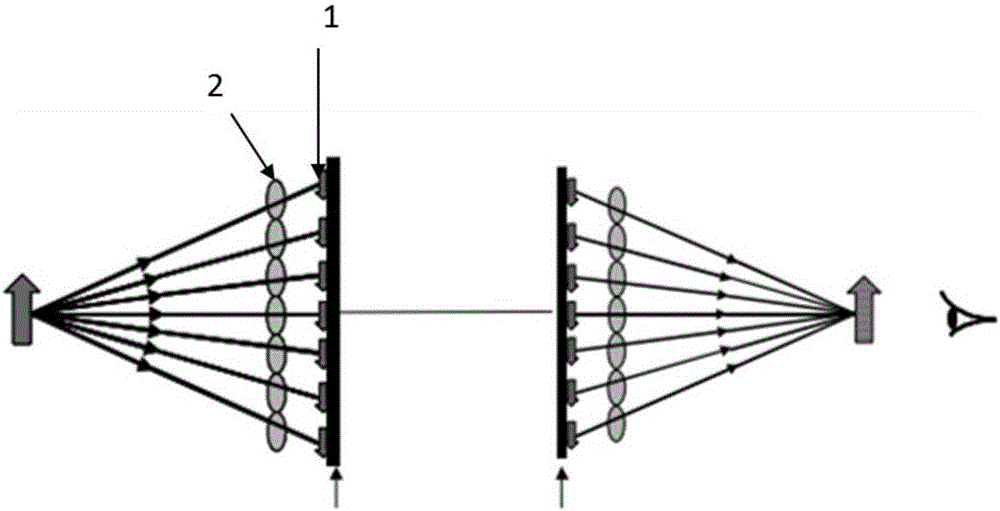
technical field [0001] The invention belongs to the technical field of three-dimensional display, and in particular relates to an integrated imaging three-dimensional display device and a method thereof. [0002] technical background [0003] Integrated imaging has full parallax, full-color 3D images, and naked-eye 3D display technology with quasi-continuous viewpoints. Integrated imaging is regarded as one of the ideal naked-eye 3D display devices. [0004] like figure 1 As shown, the integrated imaging display records and reproduces the scene in space through the microlens array 2. In the display stage, the image element 1 on the display panel optically reproduces the spatial position in the original scene in space through the corresponding microlens array 2. , forming a three-dimensional image. As the depth of the displayed 3D image increases, the edge depth planes will degenerate, resulting in an impact on the display quality of the 3D image. Existing studies have show...

Claims


Application Information

Patent Timeline
IPC IPC(8): G02B27/22G02B27/26G02F1/1335G02F1/139G02B30/25
CPCG02B30/25G02B30/27G02F1/133528G02F1/1396
Inventor 袁玲
Owner NANJING CEC PANDA LCD TECH
Learn More