Automatic identification passive tag based on visible light communication and communication system thereof

A visible light communication and automatic identification technology, which is applied in the field of optical communication, can solve problems such as environmental electromagnetic pollution, susceptibility to interference, and heating of metal objects, and achieve the effects of overcoming large electromagnetic radiation, reducing costs, and maintaining strong confidentiality

Inactive Publication Date: 2017-03-22
TIANJIN UNIV
View PDF5 Cites 8 Cited by
  • Summary
  • Abstract
  • Description
  • Claims
  • Application Information

AI Technical Summary

Problems solved by technology

[0003] However, the existing RFID technology has at least the following shortcomings and deficiencies: 1. Ordinary passive RFID tags themselves cannot generate energy, and require a very powerful reader to provide energy for the tags. Therefore, passive RFID electromagnetic radiation is large, and it is easy to cause environmental electromagnetic pollution.
And the data signal it sends is realized according to the principle of radar reflection echo, the return signal is very weak and easily interfered
2. Ultra-high frequency (UHF) RFID readers are potentially harmful to human health when they are very close to the human body. In the application of some special groups of people, such as wearable devices for pregnant women and babies, and some places with precision instruments There are great limitations in the application of
3. The high-power electromagnetic effect of RFID will make metal objects heat up, so it cannot be used in the management of dangerous objects

Method used


Image

  • Automatic identification passive tag based on visible light communication and communication system thereof
  • Automatic identification passive tag based on visible light communication and communication system thereof
  • Automatic identification passive tag based on visible light communication and communication system thereof

Examples


Embodiment Construction

[0032] The following describes in detail an automatic identification passive tag based on visible light communication and a communication system thereof of the present invention with reference to the embodiments and the accompanying drawings.

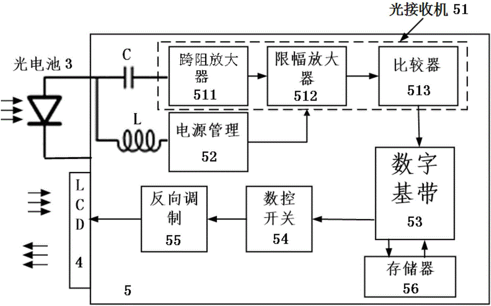
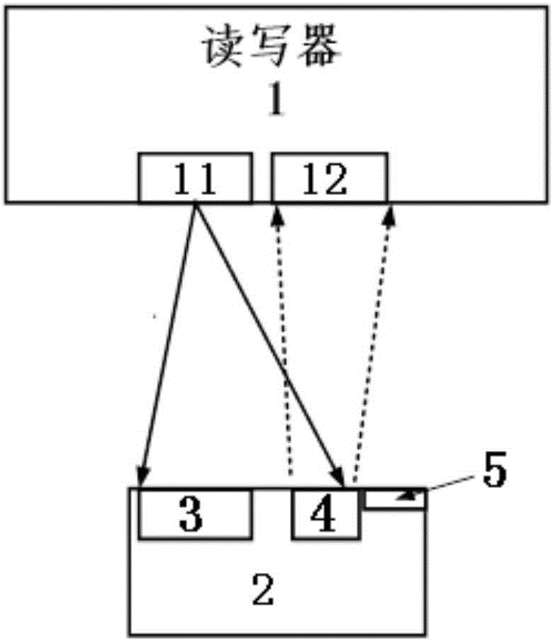
[0033] like figure 1 As shown, an automatic identification passive tag based on visible light communication of the present invention adopts the optical communication mode for the receiving signal of the tag, and the LCD modulation reflection mode for the transmitting signal. Specifically, it includes a photovoltaic cell 3 , a label chip 5 connected to the photovoltaic cell 3 , and an LCD screen 4 connected to the output of the label chip 5 for emitting light signals. The LCD liquid crystal screen 4 can adopt a liquid crystal light valve with lower modulation power consumption and lower power consumption, and has a liquid crystal light valve that is energized and light-transmitting, but is not energized and opaque. The level on-off volt...


PUM


Abstract

The invention provides an automatic identification passive tag based on visible light communication and a communication system thereof. The passive tag comprises a photocell, a tag chip connected with the photocell, and an LCD (liquid crystal display) screen connected with the output of the tag chip and used for emitting optical signals. The communication system comprises the automatic identification passive tag used for receiving light emitted by the reader-writer and reflecting information of itself to the reader-writer. A light-emitting component for emitting light to the automatic identification passive tag in the reader-writer is a light-emitting diode; and a receiving portion for receiving the optical signals reflected by the automatic identification passive tag in the reader-writer is a photoelectric detector. The automatic identification passive tag and the communication system have the advantages of bidirectional visible light communication and having a storage function; visible light communication light resources can be utilized to provide energy for an RFID (radio frequency identification) tag to realize passive work; and meanwhile, the automatic identification passive tag and the communication system also have the advantage of electromagnetic-radiation-free optical communication. The tag is long in service life, is free of cell replacement, has the functions of storage, data modification, reusability and high security, and can serve as an upgrade product of a paper-based tag.

Description

technical field [0001] The present invention relates to an optical communication. In particular, it relates to an automatic identification passive label based on visible light communication and a communication system thereof, which adopts LED to emit visible light in the downlink communication mode, and adopts LCD inverse modulation and reflects the visible light as the communication mode for the uplink communication mode. Background technique [0002] RFID electronic tags have been gradually applied to the field of identification technology. RFID electronic tags are mainly composed of three parts: tag chip, reader, data transmission and processing system. RFID electronic tags have the advantages of strong anti-interference ability, large amount of information, non-visual reading and writing, long life and many types. [0003] However, the existing RFID technology has at least the following shortcomings and deficiencies: 1. Ordinary passive RFID tags themselves cannot gener...

Claims


Application Information

Patent Timeline
Patent Type & Authority Applications(China)
IPC IPC(8): G06K19/07G06K19/077G06K17/00
CPCG06K17/00G06K19/0707G06K19/0723G06K19/07707G06K19/07749
Inventor 毛陆虹丛佳谢生肖谧
Owner TIANJIN UNIV
Why Eureka
Try Eureka