
A large spider three-dimensional motion observation and intelligent tracking device

A three-dimensional motion and intelligent tracking technology, applied in the direction of closed-circuit television system, etc., can solve the problems of inability to realize real-time observation of motion data, inability to ensure the controllability of spider motion, and lack of a set of spider stimulation devices, and achieve simple and effective structure and observation. Convenience and controllability

Active Publication Date: 2019-02-19
芜湖数字信息产业园有限公司
View PDF7 Cites 0 Cited by
  • Summary
  • Abstract
  • Description
  • Claims
  • Application Information

AI Technical Summary

Problems solved by technology

However, the observation platform of insect specimens can only observe the appearance characteristics of insects, and cannot realize real-time observation of motion data
In vivo observation currently uses a high-speed camera to shoot moving insects to obtain sequence images, and then perform three-dimensional reconstruction to obtain measurement parameters. For example, the three-dimensional observation platform established by Wang et al. in 2011 uses a high-speed camera, a channel, and a channel Plane mirrors on both sides are used to observe the movement behavior of spiders, but this observation platform does not have a set of stimulation devices for spider movement, which cannot guarantee the controllability of spider movement. Without tracking devices, real-time shooting cannot be realized. In addition, the platform cannot Get the movement information of the spider

Method used

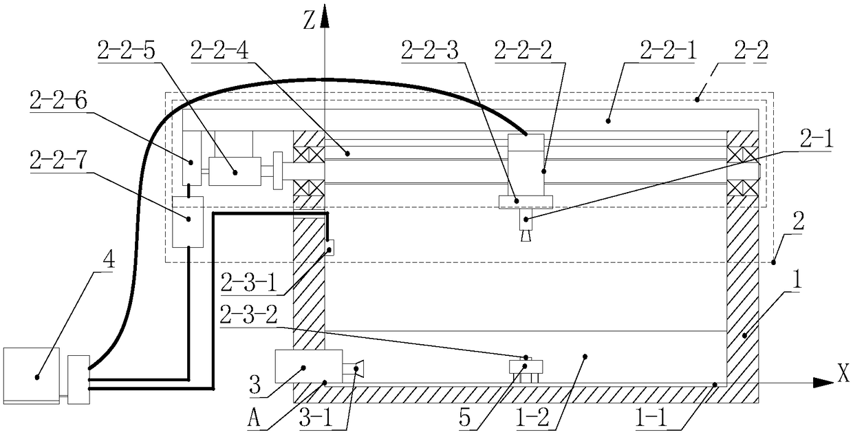
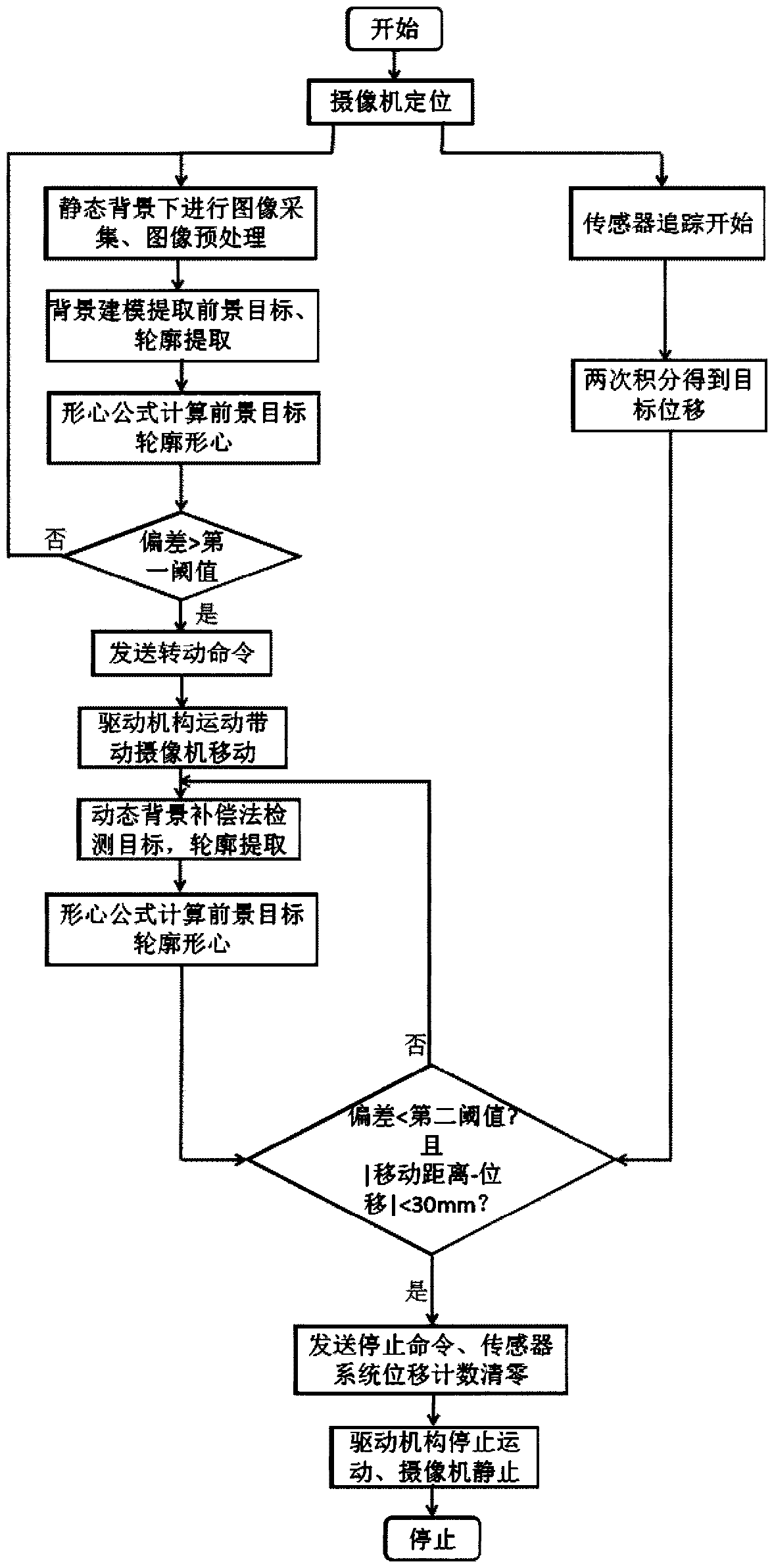

Image

  • A large spider three-dimensional motion observation and intelligent tracking device
  • A large spider three-dimensional motion observation and intelligent tracking device
  • A large spider three-dimensional motion observation and intelligent tracking device

Examples


Embodiment Construction

[0018] The present invention will be further described below in conjunction with the accompanying drawings and embodiments.

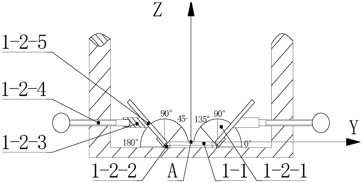
[0019] Such as figure 1 , 2 As shown, a large-scale spider three-dimensional motion observation and intelligent tracking device includes an observation box 1, an image intelligent tracking device 2, a strong light stimulation device 3 and a computer 4; a channel 1-1 is placed at the bottom of the observation box 1, and the channel 1-1 Divided into grids arranged in an array, the grids are squares with a side length of 10mm; set the coordinates of channel 1-1, the minimum scale value is 1mm, and the center of the short side of the top of the channel close to the strong light stimulation device 3 is used as the coordinate origin a. Reflective mirrors 1-2-5 are arranged on both sides of the channel 1-1, and the angle between the reflective mirror 1-2-5 and the channel 1-1 is adjusted by the mirror inclination adjustment device 1-2.

[0020] The image in...


PUM


Abstract

The invention discloses a three-dimensional motion observation and intelligent tracking device for a large spider. The existing spider three-dimensional observation platform has no motion stimulation device, and has shooting blind spots. The channel is placed at the bottom of the observation box of the present invention; reflectors are arranged on both sides of the channel, and the ball screw is supported on the observation box and driven by a servo motor; the camera installation platform and the ball screw form a spiral pair; the wireless transmitting platform is bound on the back of the spider, Both the wireless receiving platform and the high-speed camera are installed on the camera installation platform; the high-speed camera transmits the collected images to the computer; the single-chip control center receives the difference between the centroid of the spider outline obtained by the image processing module in the computer and the center of the collected image or the difference between the center of the collected image obtained by the receiving computer The wireless receiving platform transmits the displacement signal obtained after data processing, and processes the difference or displacement signal to generate a digital signal, and inputs the digital signal into the motor drive module. The present invention adopts the combination of image tracking and sensor, and can implement dynamic tracking on the observation object.

Description

technical field [0001] The invention belongs to the technical field of biological motion bionics, and in particular relates to a large spider three-dimensional motion observation and intelligent tracking device. Background technique [0002] Biomimetic robot is a robot system that imitates the external morphological characteristics or certain functions of creatures in nature. As an important research object of bionics, spiders can provide data support for the research of bionic robots through the observation of their morphological and structural characteristics and the measurement of motion parameters. The existing observation platform is relatively simple, and there are mainly two types: specimen observation and in vivo observation, among which the specimen observation: such as CN100434954C patent, discloses a patent named insect specimen observation device, which consists of three right-angle brackets, combined with Composed of three rotating shafts and a chassis, the pat...

Claims


Application Information

Patent Timeline
Patent Type & Authority Patents(China)
IPC IPC(8): H04N7/18
CPCH04N7/18
Inventor 许明吴晓萌陈国金
Owner 芜湖数字信息产业园有限公司
Learn More