Heat insulation container
A technology of container and thermal insulation layer, applied in the direction of container, large-scale container, non-pressure container, etc., can solve the problems of cracking, easy occurrence of use time, etc., achieve high thermal insulation performance, and inhibit the effect of thermal shrinkage cracking
- Summary
- Abstract
- Description
- Claims
- Application Information
AI Technical Summary
Problems solved by technology
Method used
Image
Examples
no. 1 Embodiment approach
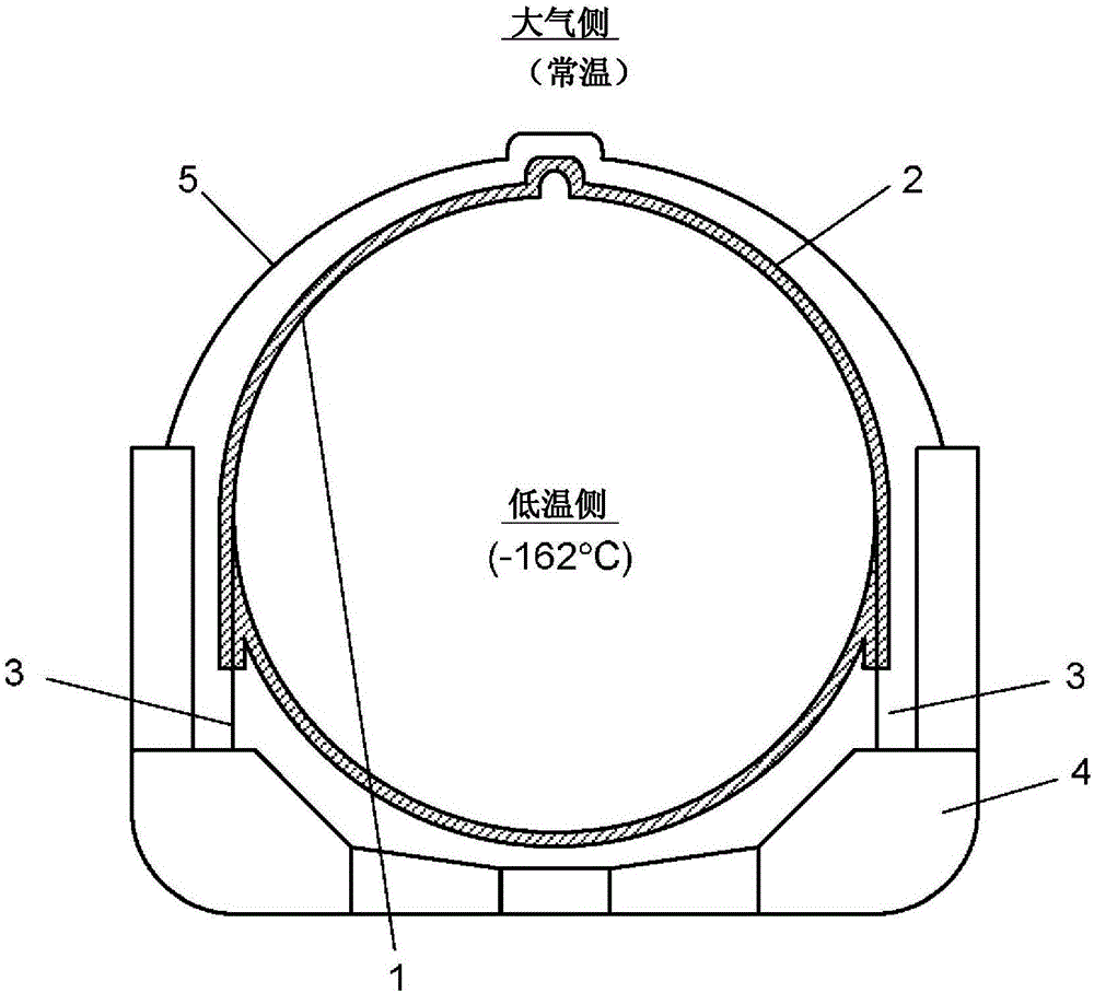
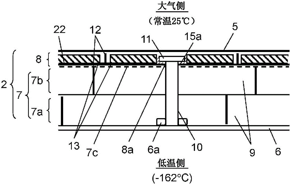
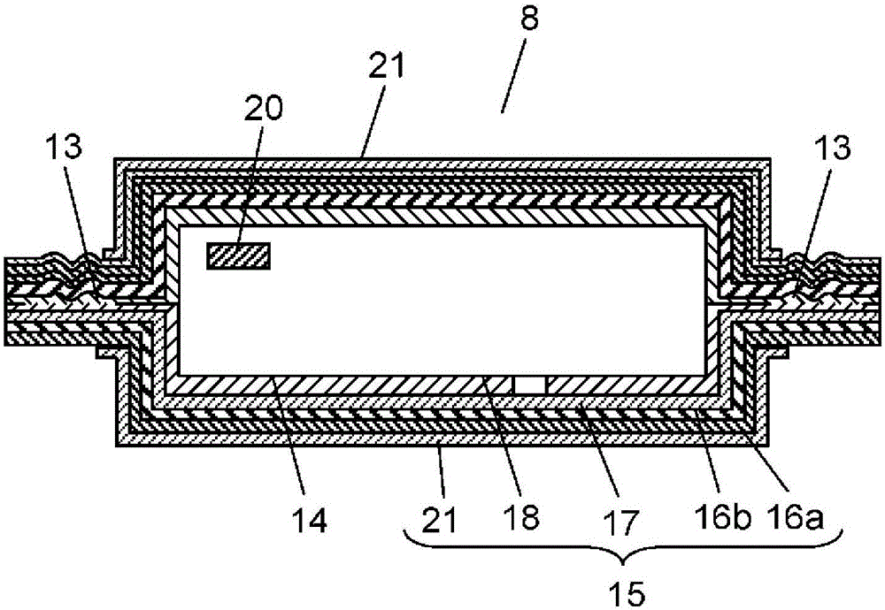
[0029] Figure 1 to Figure 5 The heat insulation container 1 in 1st Embodiment of this invention is shown.
[0030] figure 1 It is a sectional view of the heat insulation container 1 of 1st Embodiment of this invention, figure 2 is an enlarged cross-sectional view showing the heat insulating structure 2 of the heat insulating container 1, image 3 is a cross-sectional view of the vacuum heat insulating material 8 used in the heat insulating structure 2 of the heat insulating container 1, Figure 4 is a plan view of the vacuum heat insulating material 8, Figure 5 It is an explanatory drawing which shows the thermal simulation result of the heat insulation container 1 in this 1st Embodiment.
[0031] In this embodiment, the heat insulation container 1 of the spherical independent tank system (MOS system) used for an LNG tanker etc. is shown.
[0032] exist figure 1 Among them, the heat-insulated container 1 is used to store substances that are 100°C lower than normal t...
no. 2 Embodiment approach
[0092] Next, a second embodiment of the present invention will be described.
[0093] The structure of the second embodiment and Figure 1 ~ Figure 4 The structure shown is the same, but it is different in the following two points: the first heat insulating layer 7a and the second heat insulating layer 7b constituting the primary heat insulating layer 7 are formed of different kinds of materials; or, even if the same foamed benzene Ethylene also makes its foam density different, and the heat insulating performance of the second heat insulating layer 7b is equal to or higher than that of the first heat insulating layer 7a.
[0094] For example, the structure which forms the 1st heat insulating layer 7a with the expanded polystyrene of EPS similar to 1st Embodiment, and forms the 2nd heat insulating layer 7b with polyurethane foam is mentioned.
[0095] Thereby, the atmospheric temperature of the portion where the first heat insulating layer 7a is provided on the side of the co...
no. 3 Embodiment approach
[0098] Next, a third embodiment of the present invention will be described.
[0099] The structure of the third embodiment and Figure 1 ~ Figure 4 The structure shown is the same, but the layer in contact with the second heat insulating layer 7b among the first protective layer 16a and the second protective layer 16b of the outer cover 15 of the vacuum heat insulating material 8 is different from that on the opposite side. The layer in contact with the outside air has high resistance to low temperature embrittlement.
[0100] For example, the material on the side of the vacuum heat insulating material 8 that is in contact with the second heat insulating layer 7 b is a material obtained by coating the laminated film inside the thermal stress dispersion layer 21 with aluminum foil. In addition, as the material on the opposite side, which is in contact with the outside air, a material obtained by coating the laminated film inside the thermal stress dispersion layer 21 by alumin...
PUM
| Property | Measurement | Unit |
|---|---|---|
| Thermal conductivity | aaaaa | aaaaa |
Abstract
Description
Claims
Application Information
 - R&D Engineer
- R&D Manager
- IP Professional
- Industry Leading Data Capabilities
- Powerful AI technology
- Patent DNA Extraction
Browse by: Latest US Patents, China's latest patents, Technical Efficacy Thesaurus, Application Domain, Technology Topic, Popular Technical Reports.
© 2024 PatSnap. All rights reserved.Legal|Privacy policy|Modern Slavery Act Transparency Statement|Sitemap|About US| Contact US: help@patsnap.com


