Automatic powder brushing and border cutting device of chip inductor

A chip inductor and automatic brushing technology, which is applied in the manufacture of inductors/transformers/magnets, circuits, electrical components, etc., can solve the problems of reduced cutting quality, inaccurate positioning, and high production costs, and achieve stable transmission speed and accurate product positioning , good cutting quality

Active Publication Date: 2017-03-29
JINING UNICHOKA ELECTRONICS CO LTD
View PDF8 Cites 6 Cited by
  • Summary
  • Abstract
  • Description
  • Claims
  • Application Information

AI Technical Summary

Problems solved by technology

[0007] In order to solve the above technical problems, the present invention provides a chip inductor automatic powder brushing and cutting frame device, which effectively solves the problems of manual powder brushing in the process of forming chip inductors, such as low production efficiency, poor quality, and cleanliness. The effect is not good, the scrap rate of the inductance bracket is high, the production cost is high, and the problems of troublesome operation, high cost and poor cleaning effect in the automatic powder brushing; and the problem of inaccurate positioning and cutting quality in the cutting process of the inductance bracket The purpose of the problem is to provide an automatic brushing and cutting of chip inductors with simple and automatic operation, low production cost, integration of powder brushing and cutting, good cleaning effect, accurate positioning of powder brushing and cutting, and high quality of finished inductors. Frame device

Method used


Image

  • Automatic powder brushing and border cutting device of chip inductor
  • Automatic powder brushing and border cutting device of chip inductor
  • Automatic powder brushing and border cutting device of chip inductor

Examples


Embodiment 1

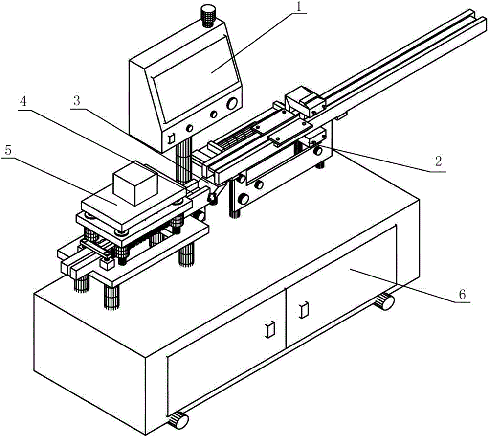
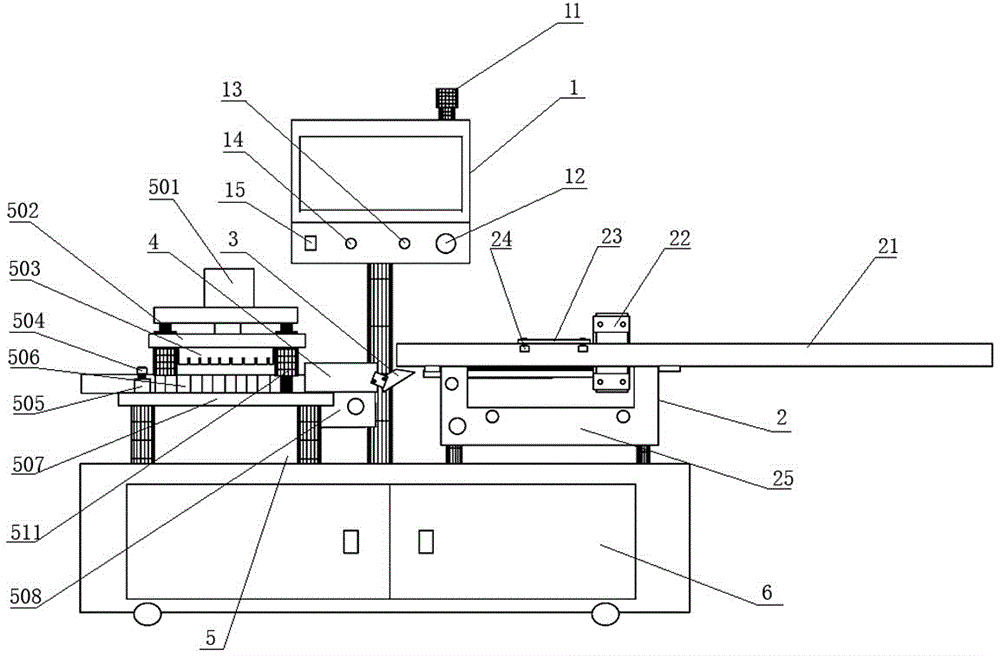
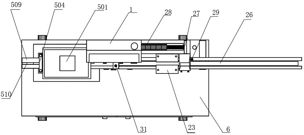
[0032] Embodiment 1: The operation process of the chip inductor automatic powder brushing and cutting frame device is: before the product starts powder coating and cutting, first check the program input preparation of the controller 1 and the operation safety of the equipment, and then press the power switch 15 and Start the switch 14, and now the first conveyor belt 26 starts to start, then put the inductance bracket directly on the first conveyor belt 26 of the powder brushing mechanism 2, and when the inductance bracket is sent to the powder brushing position and passes through the first induction light 29, the first induction light After 29 is detected, the first induction lamp 29 transmits the signal to the controller 1, and the controller 1 calculates the time for the product to reach the bottom of the splint 23 according to the length of the product according to the internally set program. When the product reaches the bottom of the splint 23 , the controller 1 drives the...


PUM


Abstract

The invention provides an automatic powder brushing and border cutting device of a chip inductor, and belongs to the technical field of chip inductor molding equipment. The device comprises a box body, a controller, a powder brushing mechanism and a border cutting mechanism, wherein the device is characterized in that the powder brushing mechanism is fixed at the right side of the upper end of the box body and comprises a first horizontal guide rail; a first conveyor belt is arranged in a groove of the first horizontal guide rail; two clamping plates are symmetrically arranged at two sides of the upper end of the first horizontal guide rail; a vertical air cylinder is arranged at the lower part of each clamping plate; a powder brushing rack is arranged at the right ends of the clamping plates; a first induction lamp is arranged at the right end of the powder brushing rack; a horizontal air cylinder is arranged at the rear part of the powder brushing rack; a second conveyor belt is arranged in a second horizontal guide rail of the border cutting mechanism, a third induction lamp is arranged at the right part of the second horizontal guide rail and pressure block control air cylinders are arranged at two sides of the second horizontal guide rail; and a cutter control air cylinder is arranged at the upper end of an upper support plate of the border cutting mechanism. The automatic powder brushing and border cutting device has the beneficial effects that the operation of the device is simple and automatic, the production cost is low, powder brushing and cutting are integrated, the cleaning effect is good, product positioning is accurate and the quality of a finished product is high.

Description

technical field [0001] The invention relates to the technical field of patch inductor forming equipment, in particular to a chip inductor automatic powder brushing and frame cutting device. Background technique [0002] The production process of one-piece chip inductor molding is: put the air-core coil into the mold of the same type, cover it with the cover plate, feed the material with the feeding device, fill the micro-gold insulating iron powder, carry out mold clamping, high-pressure die-casting, and the inductor bracket After molding, residual powder will remain on the surface of the inductance bracket. At present, in the same industry, the whole strip is manually cleaned with powder, and then the whole strip is baked. After baking, tape, paint, and fold are processed. The traditional operation method has the following problems: 1. The production efficiency of manual powder painting is low, the quality effect is not good, the cleaning effect is not good, the scrap rate ...

Claims


Application Information

Patent Timeline
Patent Type & Authority Applications(China)
IPC IPC(8): H01F41/00B08B1/00B21D28/02B21D28/14
CPCB08B1/00B21D28/02B21D28/14H01F41/00
Inventor 马高飞马肖勇陈长波
Owner JINING UNICHOKA ELECTRONICS CO LTD
Why Eureka
Try Eureka