Miniaturized high-performance microstrip filtering power divider based on zero-order resonator

A zero-order resonance, microstrip filtering technology, applied in waveguide-type devices, circuits, connecting devices, etc., can solve problems such as unfavorable engineering applications, increased cost, unsatisfactory size and performance of filter power dividers, and easy processing. , low cost and light weight

Inactive Publication Date: 2017-03-29
NANJING UNIV OF SCI & TECH
View PDF1 Cites 11 Cited by
  • Summary
  • Abstract
  • Description
  • Claims
  • Application Information

AI Technical Summary

Problems solved by technology

[0004] It can be seen from the above that the size and performance of the existing filter power dividers

Method used


Image

  • Miniaturized high-performance microstrip filtering power divider based on zero-order resonator
  • Miniaturized high-performance microstrip filtering power divider based on zero-order resonator
  • Miniaturized high-performance microstrip filtering power divider based on zero-order resonator

Examples


Embodiment 1

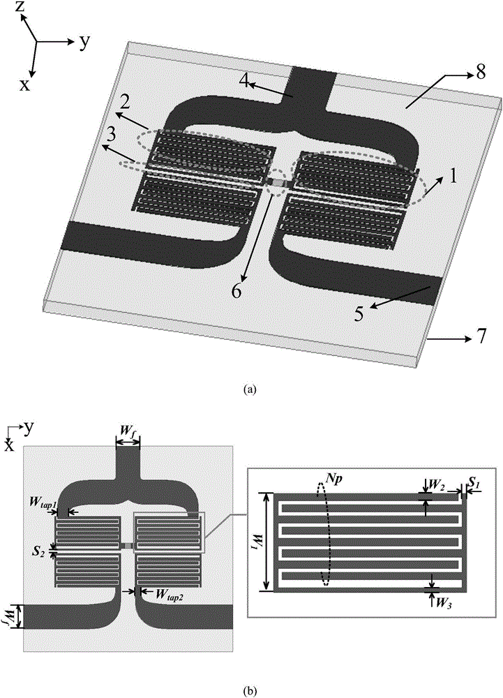
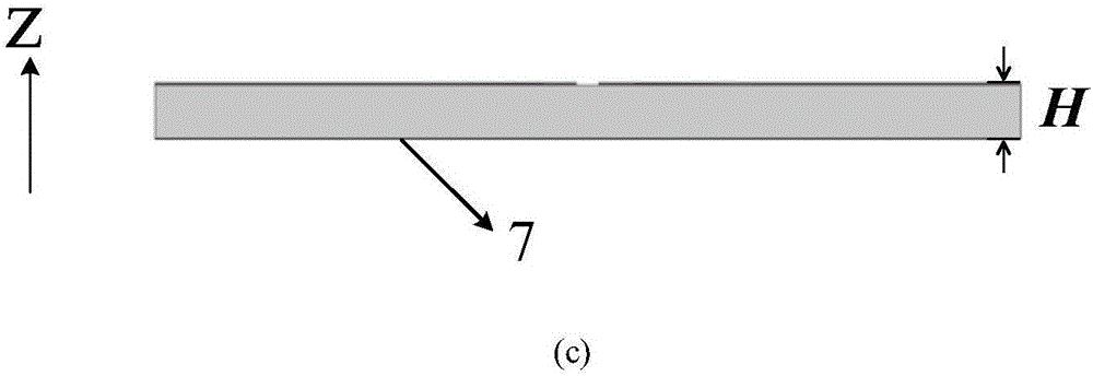
[0023] combine figure 1 , the zero-order resonator-based miniaturized high-performance microstrip filter power divider has four identical zero-order resonant units 1, upper port feeder 4, lower port feeder 5, isolation resistor 6, metal floor 7 and dielectric substrate 8, The upper port feeder 4, the lower port feeder 5, the isolation resistor 6 and the four zero-order resonant units 1 are all printed on the upper surface of the dielectric substrate 8, and a metal floor 7 is arranged below the dielectric substrate 8, and the lower port feeder 5 The number is two, and the two lower port feeders are located on both sides of the lower part of the microstrip filter power divider and are symmetrical about the central axis. The four zero-order resonant units 1 are distributed in a 2×2 matrix, and the two zeros on the top The first-order resonant units are all connected to the upper port feeder 4, the upper two zero-order resonant units are connected to an isolation resistor 6, and t...

Embodiment 2

[0028] to combine image 3 , the zero-order resonator-based miniaturized high-performance microstrip filter power divider has four identical zero-order resonant units 1, upper port feeder 4, lower port feeder 5, isolation resistor 6, metal floor 7 and dielectric substrate 8, The upper port feeder 4, the lower port feeder 5, the isolation resistor 6 and the four zero-order resonant units 1 are all printed on the upper surface of the dielectric substrate 8, and a metal floor 7 is arranged below the dielectric substrate 8, and the lower port feeder 5 The number is two, and the two lower port feeders are located on both sides of the lower part of the microstrip filter power divider and are symmetrical about the central axis. The four zero-order resonant units 1 are distributed in a 2×2 matrix, and the two zeros on the top The first-order resonant units are all connected to the upper port feeder 4, the upper two zero-order resonant units are connected to an isolation resistor 6, an...


PUM

PropertyMeasurementUnit
Thicknessaaaaaaaaaa
Gap widthaaaaaaaaaa
Center frequencyaaaaaaaaaa

Abstract

The invention discloses a miniaturized high-performance microstrip filtering power divider based on a zero-order resonator. The microstrip filtering power divider is based on a left-right-hand transmission line structure, and consists of interdigital type capacitors and high-impedance line inductors. By virtue of the characteristics of the zero-order resonator, dimensions are independent of wavelengths, so that remarkable miniaturization is realized; compared with other microstrip filtering power divider, the area of the microstrip filtering power divider disclosed by the invention is reduced by at least 50%; the filtering power divider has excellent performance, and the passband loss is only minus 3.6dB, and a passband S11 is the best of disclosed filtering power dividers, which is lower than minus 20dB; and the isolation of second and third ports achieves at least minus 19dB, which is better than that of the disclosed filtering power dividers. The microstrip filtering power divider disclosed by the invention adopts a two-sided microwave dielectric plate, so that the microstrip filtering power divider is simple in structure, easy to process, low in cost, light in weight and capable of realizing large-scale production.

Description

technical field [0001] The invention relates to a microstrip filter power divider, in particular to a miniaturized high-performance microstrip filter power divider based on a zero-order resonator. Background technique [0002] In microwave and integrated circuit systems, filters and power dividers are very important components. In many applications, the two co-exist in one system to separate microwave signals of different frequencies and realize power distribution. [0003] At present, there are two main methods to realize the two functions of filtering and power splitting at the same time: (1) directly connect the filter and the power splitter, the literature that can be referred to is: [1] R.G.Garcia, M.S.Renedo, and J.-M.M. Ferreras, “Microwave filtering power-distribution planar networks,”; [2] S.W.Wong and L.Zhu, “Ultra-wideband power divider with good in-band splitting and isolation performances,”. However, the size of the filter power dividing circuit designed by thi...

Claims


Application Information

Patent Timeline
IPC IPC(8): H01P5/12
CPCH01P5/12
Inventor 沈光煦车文荃冯文杰赵超颖
Owner NANJING UNIV OF SCI & TECH
Why Eureka
Try Eureka