
Low-voltage high-current high-breaking vacuum switch tube

A vacuum interrupter and high current technology, applied in high voltage/high current switches, high voltage air circuit breakers, circuits, etc., can solve the problems of increasing the effective space for arc diffusion and low breaking capacity of high current

Inactive Publication Date: 2017-04-05
SHANGHAI LIANGXIN ELECTRICAL
View PDF5 Cites 0 Cited by
  • Summary
  • Abstract
  • Description
  • Claims
  • Application Information

AI Technical Summary

Problems solved by technology

[0006] The purpose of the present invention is to provide a low-voltage, high-current, high-breaking circuit for the existing vacuum interrupter, which has low breaking capacity for large currents and cannot realize high-precision circuit breaker protection under low-voltage conditions. The new vacuum interrupter changes the structure of the entire vacuum interrupter, increases the effective space for arc diffusion, and improves the ability to break large currents under low voltage conditions.

Method used


Image

  • Low-voltage high-current high-breaking vacuum switch tube
  • Low-voltage high-current high-breaking vacuum switch tube

Examples


Embodiment

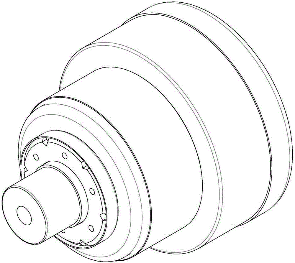
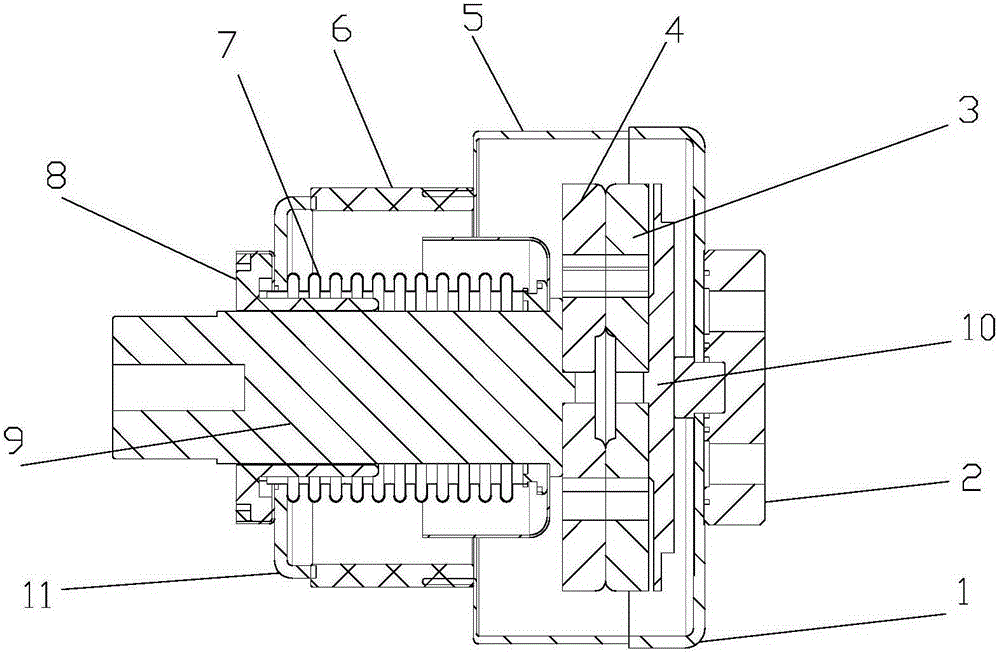
[0019] as attached figure 1 and 2 As shown, a vacuum interrupter with low voltage, high current and high breaking, which includes a static flange 1, a conductive bar 2, a static contact 3, a moving contact 4, a shielding cylinder 5, an insulating tube 6, a corrugated tube 7, The guide sleeve 8 and the moving conductive rod 9 are characterized in that: the outer diameter of the static contact 3 and the moving contact 4 is not smaller than the outer diameter of the insulating tube 6 .

[0020] The static contact 3 and the moving contact 4 are installed in the shielding cylinder 5, one end cover of the shielding cylinder is equipped with a static flange 1, the outer end of the static flange 1 is equipped with a conductive row 2, and the right end of the static contact 3 is connected to the static The bottom plate 10, the static bottom plate 10 protrude from the static flange 1 to connect with the conductive bar 2, the moving contact 4 is located on the left side of the static co...


PUM


Abstract

The invention provides a low-voltage high-current high-breaking vacuum switch tube, comprising: a static flange (1), a busbar (2), a static contact (3), a moving contact (4), a shielding cylinder (5), an insulation tube (6), a bellows (7), a direction guide sleeve (8) and a moving conductive rod (9). The outer diameters of the static contact (3) and the moving contact (4) are smaller than the outer diameter of the insulation tube (6). According to the invention, the entire vacuum switch tube structure is modified; and the effective space for electric arc diffusion is increased so that the ability of the switch tube to break and connect high current at low voltage state is increased.

Description

technical field [0001] The invention belongs to the technical field of low-voltage electrical appliances, and in particular relates to a vacuum interrupter with low voltage, high current and high breaking. Background technique [0002] Vacuum interrupter, also known as vacuum switch tube, is the core component of medium and high voltage power switch. Its main function is to quickly extinguish the arc and suppress the current after the medium and high voltage circuit is cut off through the excellent insulation of the vacuum inside the tube, so as to avoid accidents and The occurrence of accidents is mainly used in the power transmission and distribution control system of electric power, and also used in power distribution systems such as metallurgy, mining, petroleum, chemical industry, railway, broadcasting, communication, and industrial high-frequency heating. It has the characteristics of energy saving, material saving, fire prevention, explosion protection, small size, lo...

Claims


Application Information

Patent Timeline
Patent Type & Authority Applications(China)
IPC IPC(8): H01H33/664
CPCH01H33/664
Inventor 付春秋李柏晏国云
Owner SHANGHAI LIANGXIN ELECTRICAL
Learn More