Voltage and current double closed loop control method and device of adjustable invertor inertial effect

A double closed-loop control, voltage and current technology, applied in the output power conversion device, the conversion of AC power input to DC power output, wind power generation, etc. stability and other issues, to achieve the effect of being conducive to industrial promotion and application and low cost of transformation

Active Publication Date: 2017-04-05
NANJING INST OF TECH
View PDF4 Cites 11 Cited by
  • Summary
  • Abstract
  • Description
  • Claims
  • Application Information

AI Technical Summary

Problems solved by technology

However, the conventional droop control strategy can only be used for the grid-connected inverter of the voltage source type DC power supply, otherwise the grid-connected inverter cannot achieve the stability of the capacitor voltage on the DC side
[0004] 2) When the grid-connected inverter is connected to the end of the grid and the high-penetration power electronic grid, the short-circuit capacity of the grid is significantly reduced, and the dynamic support capability is significantly weakened
Since the VSG control strategy is implemented on the grid-connected inverter, the VSG control cannot ensure the stability of the capacitor voltage on the DC side, so it is only applicable to the grid-connected inverter of the voltage source DC power supply
In addition, the VSG control strategy must be equipped with a certain amount of reserves (in...

Method used


Image

  • Voltage and current double closed loop control method and device of adjustable invertor inertial effect
  • Voltage and current double closed loop control method and device of adjustable invertor inertial effect
  • Voltage and current double closed loop control method and device of adjustable invertor inertial effect

Examples


Embodiment Construction

[0026] An embodiment of an improved voltage and current double closed-loop control method that can adjust the inertia effect of the grid-connected inverter is provided, and the specific steps are as follows:

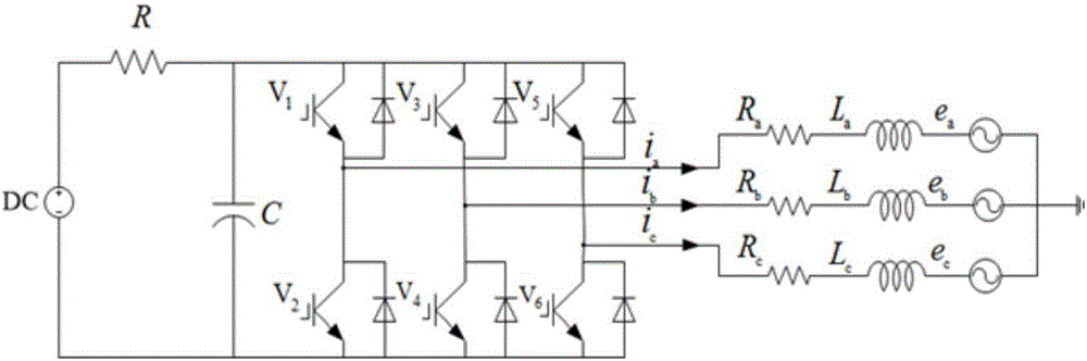
[0027] S1: Detect grid voltage, inverter output current, and inverter DC side capacitor voltage through voltage and current sensors;

[0028] S2: Get the real-time phase information of the grid voltage through the PLL operation of the detected grid voltage signal;

[0029] S3: The three-phase current output by the inverter undergoes synchronous rotation coordinate transformation to generate the inner loop current feedback value i required for current loop control d i q ;

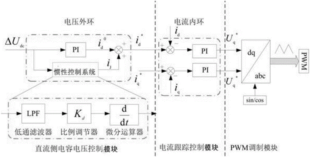
[0030] S4: Compare the detected DC side capacitor voltage signal with the given value U dc * for comparison, the difference ΔU dc As the input of the voltage outer loop, after the action of the PI controller and the inertial control system in parallel with it, the conventional current component i i...


PUM


Abstract

The present invention discloses a voltage and current double closed loop control method and device of an adjustable invertor inertial effect. In the frame of the routine voltage and current double closed loop control, the inertial current component is added in an inverter current inner ring instruction to realize the equivalent control of the inverter inertia property and is indirectly generated through an inertial control system connected in parallel on the voltage outer ring. The inertial control system is formed by three parts connected in series, wherein the three parts include a low pass filter, a proportional controller and a differential arithmetical unit. The size of the inertial current component and the intensity level of the grid-connected inverter inertial effect can be flexibly controlled through the proportional controller in the inertial control system. The voltage and current double closed loop control method of the adjustable invertor inertial effect does not need to change the hardware portion of the current grid-connected inverter system, completely maintains the current basic control frame of the software portion, has good compatibility, can be applied to a double-fed wind turbine system and a photovoltaic power generation system, and has good engineering application values.

Description

technical field [0001] The invention belongs to the technical field of grid-connected inverter control, and in particular relates to an improved voltage-current double-closed-loop control technology capable of adjusting the inertia effect of a grid-connected inverter. Background technique [0002] With the increasing penetration of new energy sources such as photovoltaics and wind power, grid-connected inverters characterized by low inertia and weak damping are connected to the power system on a large scale. The conventional rotary synchronous generator (Rotational Synchronous Generator, RSG) The proportion of installed capacity gradually decreases, resulting in a relative reduction in the rotating reserve capacity and moment of inertia in the power system; on the other hand, new energy power represented by wind energy and solar energy has low-density dispersion on the spatial scale and strong random fluctuations on the time scale Large-scale new energy access will lead to s...

Claims


Application Information

Patent Timeline
IPC IPC(8): H02M7/5387H02J3/38
CPCH02J3/38H02M7/5387Y02E10/76
Inventor 熊连松王东杰林健李秋月
Owner NANJING INST OF TECH
Why Eureka
Try Eureka