
A detection method for the pressure distribution of the oil cavity of the hydrostatic guide rail

A technology of hydrostatic guide rail and oil chamber pressure, which is applied in the direction of measuring/indicating equipment, metal processing machinery parts, metal processing equipment, etc. It can solve the problems of difficult to accurately obtain the oil chamber pressure and limited space, and achieve convenient measurement , convenient and consistent effect

Active Publication Date: 2018-05-22
HARBIN INST OF TECH
View PDF6 Cites 0 Cited by
  • Summary
  • Abstract
  • Description
  • Claims
  • Application Information

AI Technical Summary

Problems solved by technology

However, the internal space of the oil chamber of the hydrostatic guide rail is limited, the distance between the moving part and the guide rail base is tens of microns, and the high-pressure oil communicates with the atmosphere through the oil seal edge, and the pressure drops rapidly. It is difficult to change the structure of the guide rail. The oil chamber pressure is directly measured under the premise; the oil chamber pressure is mostly measured only by measuring the oil supply pressure, and then calculating the oil chamber pressure based on experience. This method is difficult to accurately obtain the oil chamber pressure, especially for different guide rails. It is difficult to propose a general empirical formula and method for oil chamber pressure estimation

Method used


Image

  • A detection method for the pressure distribution of the oil cavity of the hydrostatic guide rail
  • A detection method for the pressure distribution of the oil cavity of the hydrostatic guide rail

Examples


Embodiment Construction

[0023] The technical solution of the present invention will be further described below in conjunction with the accompanying drawings, but it is not limited thereto. Any modification or equivalent replacement of the technical solution of the present invention without departing from the spirit and scope of the technical solution of the present invention should be covered by the present invention. within the scope of protection.

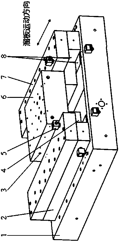
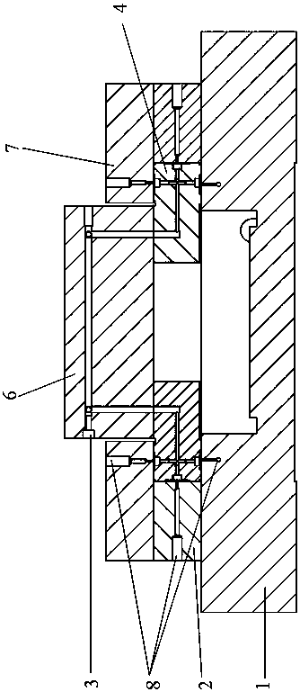
[0024] like figure 1 As shown, the detection device for the pressure distribution of the hydrostatic guide rail oil chamber provided by the present invention includes a guide rail base 1, a guide rail side plate 2, an oil inlet channel 3, an oil chamber module 4, a pressure sensor 5, a sliding plate 6, a guide rail pressing plate 7, Pressure measurement channel 8. in:

[0025] The guide rail side plate 2, the guide rail pressure plate 7 and the guide rail base 1 form a guide rail, the guide rail side plate 2 is fixedly installed on the guide rail base...


PUM


Abstract

The invention discloses a method for detecting the pressure distribution in an oil cavity of a hydrostatic guideway. The method comprises the following steps: 1, hydraulic oil is sent by a hydraulic station into each oil cavity through an oil inlet channel and a throttling device, so that a guideway moving part can be floated; 2, the guideway moving part is moved to an oil cavity pressure measuring station, pressure oil in the oil cavity enters a pressure measuring channel, a pressure sensor takes a signal pressure signal as the input and begins to read the pressure value at a certain positon in the oil cavity, and the signal processing and the real-time display are performed; 3, after that, the oil cavity pressure of a corresponding position is recorded each time after the guideway moving part is moved by a small displacement, so that a curve of the pressure distribution in the oil cavity of the hydrostatic guideway can be obtained; and 4, according to the obtained curve of the pressure distribution, the impact of the pressure distribution in the oil cavity on the performance of the hydrostatic guideway is researched. According to the method disclosed by the invention, an oil cavity pressure testing point is arranged on the hydrostatic guideway, thereby effectively solving the problem about how to detect the pressure distribution in the oil cavity of the hydrostatic guideway.

Description

technical field [0001] The invention relates to a method for detecting important technical parameters of a hydrostatic pressure support part of an ultra-precision machining machine tool, in particular to a method for detecting the pressure distribution of an oil chamber of a hydrostatic guide rail. Background technique [0002] Hydrostatic guideway is an important supporting part of ultra-precision machining machine tools. It has the characteristics of high motion precision, large load capacity, high rigidity, good damping characteristics, small creeping, and good vibration isolation performance. The hydrostatic guide rail relies on the oil cushion formed between the moving parts and the base to play a supporting role. During the design and assembly process of the hydrostatic guide rail, the pressure of the oil chamber can be adjusted by installing a restrictor at the oil inlet of each oil chamber. , The purpose of improving the stiffness of the guide rail. The oil chamber ...

Claims


Application Information

Patent Timeline
Patent Type & Authority Patents(China)
IPC IPC(8): B23Q17/00
CPCB23Q17/00B23Q17/007
Inventor 王波刘远航乔政吴言功赖志锋
Owner HARBIN INST OF TECH
Learn More