Rod port deburring machine

A technology for deburring machines and rods, which is applied in the direction of machine tools, grinding racks, and grinding workpiece supports suitable for grinding the edge of workpieces. It can solve the problems of unsuitable processing of rods and achieve good processing results.

Inactive Publication Date: 2017-04-19
杭州钱江万胜电器制造有限公司
View PDF5 Cites 1 Cited by
  • Summary
  • Abstract
  • Description
  • Claims
  • Application Information

AI Technical Summary

Problems solved by technology

This technical solution is mainly aimed at deburring castings, and is not suitable for processing rods and pipes.

Method used


Image

  • Rod port deburring machine

Examples


Embodiment Construction

[0017] The present invention will be further described below in conjunction with the accompanying drawings and specific embodiments.

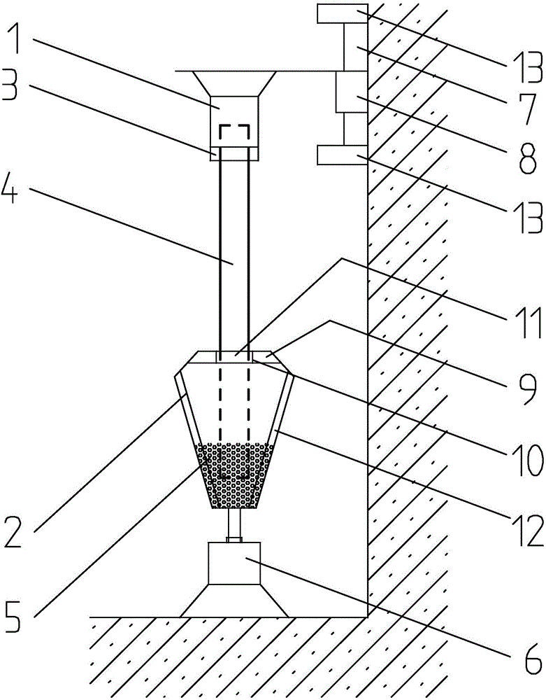
[0018] This embodiment is a rod end deburring machine, which is applied in a copper pipe processing workshop. Such as figure 1 As shown, the rod end deburring machine includes two sets of main structural parts, one is the abrasive pot 2 on the ground and the abrasive pot rotating motor 6, etc., and the other is the clamping rod motor 1 and the linear reciprocating motor fixed on the side wall 8 etc.

[0019] The abrasive pot is a pot body whose diameter is large at the top and small at the bottom, and the bottom is connected with the rotating motor of the abrasive pot, and can rotate around the axis under the drive of the rotating motor of the abrasive pot. The inner wall of the abrasive pot is provided with a plurality of ribs 12 equidistant along the axial direction, and the abrasive pot is provided with granular abrasives 5, the abrasive u...


PUM


Abstract

The invention discloses a rod port deburring machine which comprises a rod clamping motor and an abrasive tank; a motor shaft of the rod clamping motor is connected with a rotatable rod clamp; the rod clamp adaptively clamps the rod; granular abrasives are arranged in an inside space of a body of the abrasive tank; and the burr end of the rod is submerged into the abrasives. The rod port deburring machine has the beneficial effects that deburring treatment can be carried out on the end surfaces of a metal rod and a pipe fitting pointedly and particularly has very good treatment effect aiming at a fracture with an irregular shape.

Description

technical field [0001] The invention relates to a metal processing equipment, in particular to a deburring machine for a rod end. Background technique [0002] Metal rods need to be cut to appropriate lengths before use. The most common cutting method is sawing, and the side of the sawn section usually has a lot of burrs. If these burrs are not cleaned up, they will pose hidden dangers to product quality and employee safety. Chinese patent document CN 101185981A disclosed a "scraper type deburring machine device" on May 28, 2008, which is characterized in that: the two ends of the traverse device are connected with the traverse cylinder and buffer of the push device; the lower end passes through the wheel shaft guide rail The rack and pinion under the device is connected with the pushing device, and the moving device moves back and forth along the rack in the rack and pinion through the traversing cylinder, and drives the tool on the tool seat to move to remove the burr of...

Claims


Application Information

Patent Timeline
IPC IPC(8): B24B31/00B24B41/06B24B9/04B24B9/00B24B41/02
CPCB24B31/003B24B9/007B24B9/04B24B41/02B24B41/067
Inventor 徐青会
Owner 杭州钱江万胜电器制造有限公司
Why Eureka
Try Eureka