
Prefabricated steel-concrete combined beam-column frame structure system

A hybrid combined beam and frame structure technology, applied in building structure, construction, etc., can solve the problems of difficult anti-corrosion and fire prevention treatment technology, complex node connection structure, slow construction speed, etc., to save external formwork materials and improve labor conditions for workers , easy-to-control effects

Active Publication Date: 2019-02-19
SHAOXING UNIVERSITY
View PDF6 Cites 0 Cited by
  • Summary
  • Abstract
  • Description
  • Claims
  • Application Information

AI Technical Summary

Problems solved by technology

The concrete frame structure system is mainly constructed by the cast-in-place method, and the construction speed is slow, and this construction mode has problems such as high energy consumption, high pollution, low efficiency, and extensive construction, which is inconsistent with the current development requirements of new urbanization, industrialization, and informationization. Adaptation; the steel frame structure system can be welded and bolted, and the construction speed is fast, but its construction cost is high, the anti-corrosion and fire prevention treatment technology is difficult, and the maintenance cost after delivery is high; in recent years, the following composite frame systems have appeared: Concrete beam frame system, steel tube concrete column-steel beam frame system, steel tube concrete-steel reinforced concrete beam and reinforced concrete column-steel beam frame system, but there are still some deficiencies in the design and construction, and the joint connection structure is relatively complicated. Its connection nodes are carefully designed and professionally constructed, which is prone to structural integrity problems

Method used


Image

  • Prefabricated steel-concrete combined beam-column frame structure system
  • Prefabricated steel-concrete combined beam-column frame structure system
  • Prefabricated steel-concrete combined beam-column frame structure system

Examples


Embodiment 1

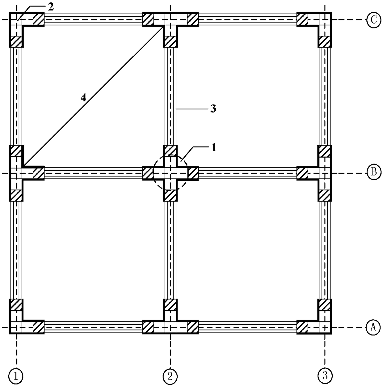
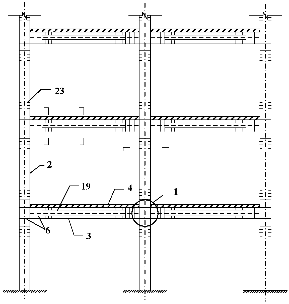
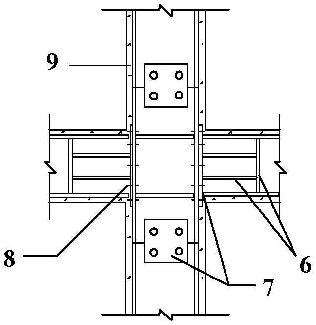
[0038] Prefabricated steel-concrete combined beam-column frame structure system, the plan view and elevation view of the frame system are as follows Figure 1~2 As shown, the frame system is composed of steel nodes 1, steel-concrete combined columns 2, steel-concrete combined beams 3, and laminated plates 4; the steel nodes are as follows image 3 As shown, the stiffener 6 is welded in the middle of the section steel 5 to increase the stiffness of the joint, the connecting plate 7 is connected with the web end of the section steel 5 through the bolt 8, and at the same time, welding is used at the joint to further strengthen the connection performance between them, and at the steel node 1. Concrete protection layer 9 is poured outside; the cross-section of the steel-concrete combined column 2 is square such as Figure 4As shown, the concrete column 10 is equipped with steel bars 13. The specific size and reinforcement ratio of the concrete column 10 are calculated according to ...


PUM


Abstract

The invention discloses an assembly type steel-concrete combined beam column frame structure system. The assembly type steel-concrete combined beam column frame structure system comprises a steel joint, a steel-concrete combined column, a steel-concrete combined beam and a laminated slab. The steel joint comprises profile steel, a stiffening rib, a connection plate and a bolt, and a concrete protection layer is poured outside the steel joint. The steel-concrete combined column comprises a concrete column, a steel-concrete combined section, a short steel column, a rebar, a drilling device, a finish-rolled deformed bar and an anchoring nut. The steel-concrete combined beam comprises a concrete beam, a steel-concrete combined section, a short steel beam, a rebar, a drilling device, an anchoring device, a prestressed cable and a beam end connection plate. The laminated slab comprises a precast concrete slab and a cast-in-place layer. After the precast concrete slab is installed in place, the concrete cast-in-place layer is poured on the precast concrete slab. The assembly type steel-concrete combined beam column frame structure system combines the advantages of a cast-in-place concrete frame system and a steel structure frame system and has good mechanical performance, economic indicators and a very high prefabrication assembly rate which can reach 100%. Fast assembly construction is adopted, and the construction period is shortened effectively.

Description

technical field [0001] The invention belongs to the technical field of construction engineering, and in particular relates to an assembled steel-concrete combined beam-column frame structure system. Background technique [0002] Frame system is the most extensive form of building structure, divided into concrete frame structure system and steel frame structure system, mainly used in shopping malls, office buildings, schools and other multi-storey structures that require flexible space division. The concrete frame structure system is mainly constructed by the cast-in-place method, and the construction speed is slow, and this construction mode has problems such as high energy consumption, high pollution, low efficiency, and extensive construction, which is inconsistent with the current development requirements of new urbanization, industrialization, and informationization. Adaptation; the steel frame structure system can be welded and bolted, and the construction speed is fast...

Claims


Application Information

Patent Timeline
Patent Type & Authority Patents(China)
IPC IPC(8): E04B1/30
CPCE04B1/30
Inventor 何余良吴旭东
Owner SHAOXING UNIVERSITY
Learn More