
Electro-optic modulator based on Si-VO2 composite waveguide

An electro-optic modulator and composite waveguide technology, which is applied in instruments, optics, nonlinear optics, etc., can solve the problems of slow speed of thermo-optic effect, large size, limited range of refractive index adjustment, etc., and achieves fast modulation speed, simple structure, low cost effect

Active Publication Date: 2017-04-19
SHANGHAI JIAO TONG UNIV
View PDF3 Cites 20 Cited by
  • Summary
  • Abstract
  • Description
  • Claims
  • Application Information

AI Technical Summary

Problems solved by technology

However, the thermo-optic effect is relatively slow, usually on the order of microseconds; although the response time of the carrier dispersion effect is fast, the adjustment range of the refractive index is limited, and the change of the refractive index is usually on the order of 10-3, so in order to realize 180-degree phase change, the length of the device needs to be on the order of millimeters, resulting in high-speed modulators and optical switch devices usually having large dimensions

Method used


Image

  • Electro-optic modulator based on Si-VO2 composite waveguide
  • Electro-optic modulator based on Si-VO2 composite waveguide
  • Electro-optic modulator based on Si-VO2 composite waveguide

Examples


Embodiment Construction

[0022] The embodiments of the present invention will be described in detail below in conjunction with the accompanying drawings and Examples. This embodiment is implemented on the premise of the technical solution of the present invention, and detailed implementation methods and operating procedures are provided, but the protection scope of the present invention is not limited to Examples described below.

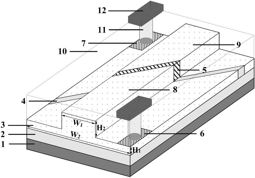
[0023] figure 1 It is a structural schematic diagram of an embodiment of the electro-optic modulator based on Si-VO2 composite waveguide of the present invention, including: from bottom to top: silicon substrate 1, silicon dioxide lower cladding layer 2, ridge waveguide layer 3, two An upper cladding layer 10 of silicon oxide, a metal via 11 , and a metal electrode layer 12 .

[0024] Among them, the thickness of the lower cladding layer 2 of silicon dioxide is 2 μm, and the height of the plate part of the ridge waveguide layer 3 is H 1 60nm, ridge waveguide 3 convex heig...


PUM

PropertyMeasurementUnit
heightaaaaaaaaaa
heightaaaaaaaaaa
widthaaaaaaaaaa

Abstract

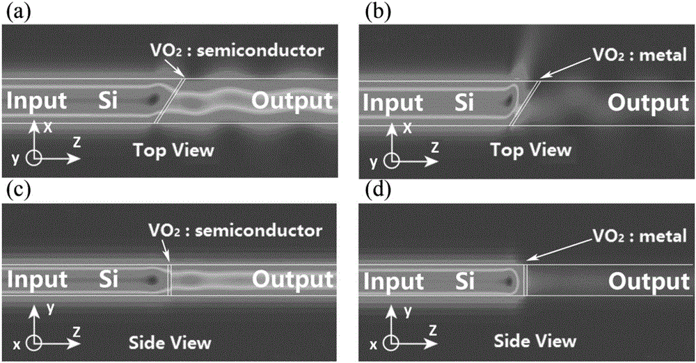
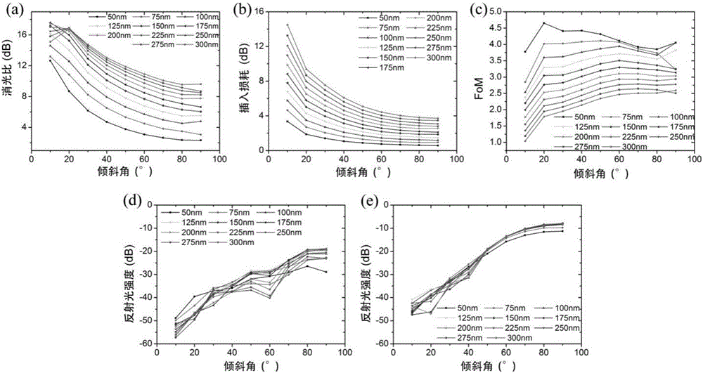
The invention discloses an electro-optic modulator based on a Si-VO2 composite waveguide. The modulator comprises a silicon substrate, a SiO2 lower cladding, a ridge waveguide, a SiO2 upper cladding, and a metal electrode layer. The ridge waveguide is carved with a slot. A protruding strip is filled with VO2 to form the Si-VO2 composite waveguide. A flat board on two sides is filled with SiO2 for insulation. A P-type lightly doped region and an N-type lightly doped region on two sides of the slot form a PN junction. Metal electrodes are connected with heavily doped regions on two sides of the flat board. The modulator uses phase changes of ViO2 under the force of electric field to induce changes of refraction rate so as to achieve modulation. The modulator is simple in structure, high in modulation extinction ratio, and low in insertion loss. Meanwhile, the inclined ViO2 slot structure is utilized to increase the length of effect and reduce the intensity of reflected light. The modulator has wide application prospect in the field of optical communication and integrated optoelectronics.

Description

technical field [0001] The invention relates to electro-optic modulation technology in silicon-based integrated optoelectronics, in particular to an electro-optic modulator based on Si-VO2 composite waveguide. Background technique [0002] Silicon-based optoelectronic devices have become an indispensable part of the future development of optical communication technology due to their advantages of low power consumption, low cost, miniaturization, and compatibility with traditional microelectronic processing techniques. As one of the key devices of electro-optical conversion in optical transmission network, modulator has always been the focus of researchers, and its performance will directly affect the quality of the entire optical communication system. [0003] Generally, silicon-based integrated optoelectronic devices change the refractive index characteristics of silicon materials through thermo-optic effect or carrier dispersion effect, so as to realize active adjustment. ...

Claims


Application Information

Patent Timeline
Patent Type & Authority Applications(China)
IPC IPC(8): G02F1/035G02F1/03
CPCG02F1/0305G02F1/035
Inventor 周林杰孙照印陆梁军张涵予陈建平
Owner SHANGHAI JIAO TONG UNIV
Learn More