A microwave frequency conversion circuit and frequency converter
A microwave frequency conversion and circuit technology, applied in the microwave field, can solve the problems of signal interference, low circuit stability, poor isolation effect of electronic components, etc., and achieve the effects of reducing interference, simple circuit structure, and less peripheral circuits.
- Summary
- Abstract
- Description
- Claims
- Application Information
AI Technical Summary
Problems solved by technology
Method used
Image
Examples
Embodiment 1
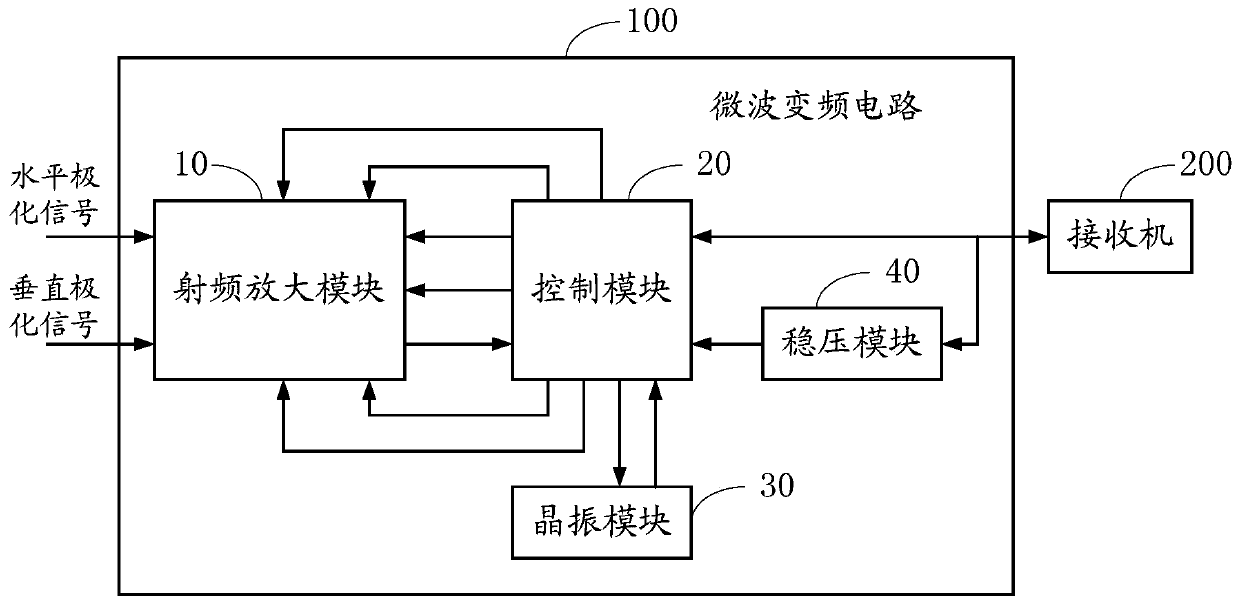
[0017] Such as figure 1 As shown, the microwave frequency conversion circuit 100 provided in this embodiment includes a radio frequency amplification module 10 , a highly integrated control module 20 , a crystal oscillator module 30 and a voltage stabilization module 40 .
[0018] The first input controlled end of the radio frequency amplification module 10 is connected to the horizontal polarization signal and connected with the first control end of the control module 20, and the first controlled end of the radio frequency amplification module 10 is connected with the second control end of the control module 20, The second input controlled terminal of the radio frequency amplification module 10 is connected to the vertical polarization signal and connected with the third control terminal of the control module 20, and the second controlled terminal of the radio frequency amplification module 10 is connected with the fourth control terminal of the control module 20, The third c...
Embodiment 2
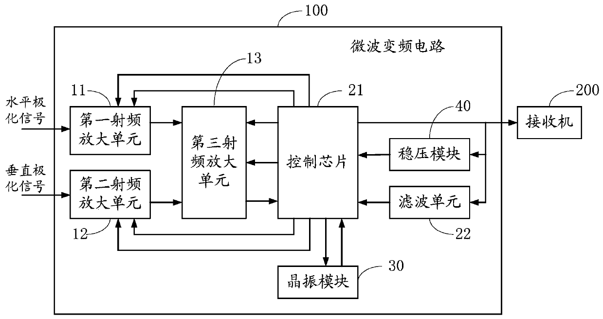
[0027] Such as figure 2 As shown, in this embodiment, the radio frequency amplification module 10 includes a first radio frequency amplification unit 11 , a second radio frequency amplification unit 12 and a third radio frequency amplification unit 13 .
[0028] The input controlled terminal of the first radio frequency amplifying unit 11 is the first input controlled terminal of the radio frequency amplifying module 10, the output controlled terminal of the first radio frequency amplifying unit 11 is the first controlled terminal of the radio frequency amplifying module 10, the first radio frequency The controlled output terminal of the amplifying unit 11 is also commonly connected with the controlled output terminal of the second radio frequency amplifying unit 12 and the controlled input terminal of the third radio frequency amplifying unit 13 .
[0029] The controlled input terminal of the second radio frequency amplifying unit 12 is the second controlled input terminal o...
Embodiment 3
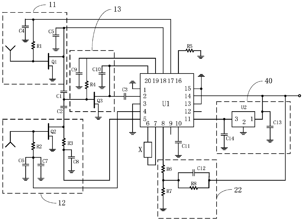
[0040] Such as image 3 As shown, in this embodiment, the radio frequency amplification module 10 further includes a first coupling capacitor C1, a second coupling capacitor C2 and a third coupling capacitor C3.
[0041] The anode of the first coupling capacitor C1 is connected to the output controlled terminal of the first radio frequency amplifying unit 11, the anode of the second coupling capacitor C2 is connected to the output controlled terminal of the second radio frequency amplifying unit 12, and the cathode of the first coupling capacitor C1 and the second The cathode of the coupling capacitor C2 is commonly connected to the input controlled terminal of the third radio frequency amplifying unit 13;
[0042] The anode of the third coupling capacitor C3 is connected to the output controlled terminal of the third radio frequency amplifying unit 13, and the cathode of the third coupling capacitor C3 is connected to the radio frequency signal input terminal (i.e., the contr...
PUM
 Abstract
Description
Claims
Application Information
 - R&D
- Intellectual Property
- Life Sciences
- Materials
- Tech Scout
- Unparalleled Data Quality
- Higher Quality Content
- 60% Fewer Hallucinations
Browse by: Latest US Patents, China's latest patents, Technical Efficacy Thesaurus, Application Domain, Technology Topic, Popular Technical Reports.
© 2025 PatSnap. All rights reserved.Legal|Privacy policy|Modern Slavery Act Transparency Statement|Sitemap|About US| Contact US: help@patsnap.com


