
Straight pipe header coil pipe type reactor for waterway natural circulation

A tubular reactor, natural circulation technology, applied in the fields of carbon monoxide or formate reaction preparation, chemical instruments and methods, preparation of organic compounds, etc. problems, to achieve the effect of convenient and simple filling and self-unloading, high overall heat transfer coefficient, and reduced floor space

Pending Publication Date: 2017-04-26
NANJING DUNXIAN CHEM TECH
View PDF10 Cites 5 Cited by
  • Summary
  • Abstract
  • Description
  • Claims
  • Application Information

AI Technical Summary

Problems solved by technology

The tubes of the carbonylation reactor are φ25×2~φ32×2. Currently, the maximum production capacity of ethylene glycol that has been put into operation in the market is 100,000 tons of ethylene glycol. The specification of the carbonylation reactor is φ6000H 催 = 8000 specifications, due to incomplete elimination of thermal stress, high bed resistance, reactor leakage, and the device is in a shutdown state
The ethylene glycol plant put into operation in many places in the market has an actual single series of ethylene glycol production capacity of 50,000 tons, and two series of 200,000 tons of ethylene glycol carbonylation reaction, four φ4600, H 催 =6000 carbonylation reactors are operated in parallel, and there are defects such as less catalyst loading, poor heat transfer capacity, large resistance, high energy consumption, easy decomposition and explosion, many side reactants, easy burn-through of tube sheets, and difficulty in scaling up the device;
[0005] The heat exchange element of the plate carbonylation reactor is surrounded by several rectangular parallelepiped plates of 150-400 (plate width)×H (plate height), which is actually a polygonal surface, and the thickness of the catalyst will be uneven. , local overheating of the catalyst bed is prone to occur, and it is not suitable for carbonylation reaction in actual engineering, because methyl nitrite begins to undergo thermal decomposition reaction at 140 °C, and methyl nitrite will completely thermally decompose at 155-160 °C. Moreover, the thermal decomposition reaction releases a large amount of heat (3216j / g CH 3 ONO), which is also a volume increase reaction (2CH 3 ONO→CH 3 OH+CH 2 O+2NO), leading to a rapid increase in temperature and pressure, which will inevitably cause accidents

Method used


Image

  • Straight pipe header coil pipe type reactor for waterway natural circulation
  • Straight pipe header coil pipe type reactor for waterway natural circulation
  • Straight pipe header coil pipe type reactor for waterway natural circulation

Examples


Embodiment 1

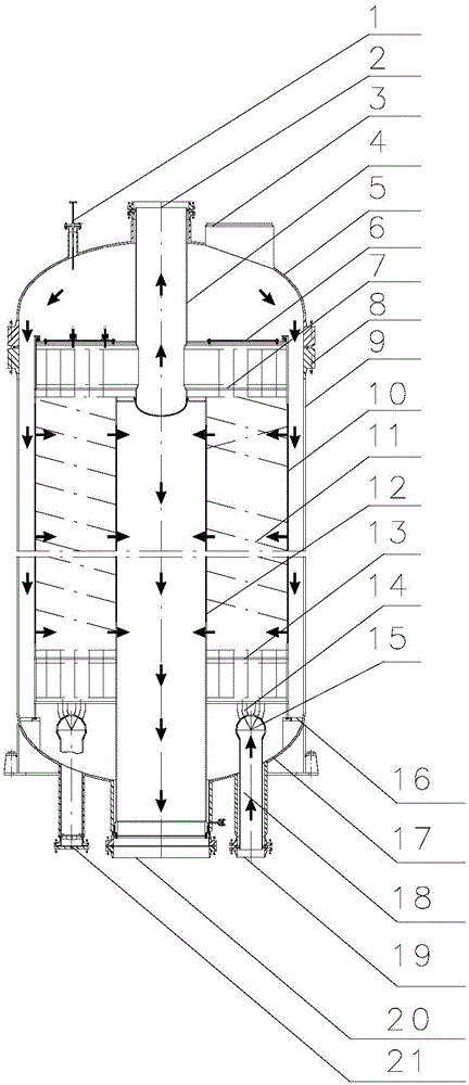
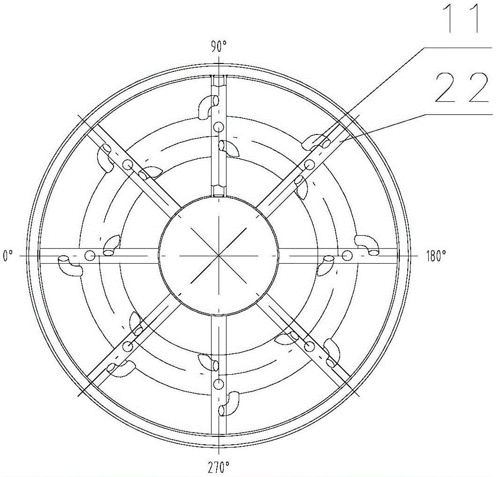
[0036] like figure 1As shown, this embodiment includes a pressure-bearing shell, a catalyst frame and a heat exchange tube bundle, and the catalyst frame and heat exchange tube bundle are respectively arranged in the pressure-bearing shell; the heat exchange tube bundle includes an outlet pipe 4, an upper straight pipe Header 7, snake pipe 11, lower straight pipe header 13, branch pipe 14, ring pipe 15 and water inlet pipe 18, the outlet pipe 4 is connected to the top of the pressure-bearing shell, and the upper straight pipe header 7 is respectively connected to the The inlet of the water pipe 4 and the outlet of the coil pipe 11, the coil pipe 11 is distributed along the axial direction of the pressure-bearing shell, the lower straight pipe header 13 is respectively connected to the inlet of the coil pipe 11 and the outlet of the branch pipe 14, the inlet The water pipe 18 is connected to the bottom of the pressure housing, and the annular pipe 15 is respectively connected t...

Embodiment 2

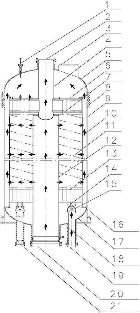
[0045] like figure 2 Shown, the present embodiment uses reactor to carry out the method for carbonylation reaction, comprises the following steps:

[0046] (21) Palladium series catalyst is filled in the catalyst frame;

[0047] (22) In the coiled pipe 11, water flows from bottom to top, and the lower gas port 20 enters the reaction gas, passes through the catalyst bed in the radial direction through the inner gas cylinder 12 to the outer gas cylinder 10, and carbonylation reaction occurs;

[0048] (23) After the reaction, the water phase change in the coiled pipe 11 absorbs heat, and the heat of the carbonylation reaction in the catalyst frame is removed, and the gas is collected by the outer gas cylinder 10, and then discharged through the upper gas port 3 and takes away the heat.

[0049] Using the reactor of this embodiment, 2CH can be completed 3 ONO+2CO=CH 3 OCOCOCH 3 O+2NO+Q 放 、2CH 3 ONO+CO=CH 3 OCOCH 3 O+2NO+Q 放 、2CH 3 ONO=HCHO+CH 3 OH+2NO+Q 放 Waiting for ...


PUM

PropertyMeasurementUnit
angleaaaaaaaaaa

Abstract

The invention discloses a straight pipe header coil pipe type reactor for waterway natural circulation. The heat exchange pipe bundles comprise a water outlet pipe, an upper straight pipe header, coil pipes, a lower straight pipe header, branch pipes, annular pipes and a water inlet pipe, the water discharge pipe is connected to the top of a pressure-loaded housing, the upper straight pipe header is connected to an inlet of the water discharge pipe and outlets of the coil pipes respectively, the coil pipes are distributed in the axial direction of the pressure-loaded housing, the lower straight pipe header is connected to inlets of the coil pipes and outlets of the branch pipes respectively, the water inlet pipe is connected to the bottom of the pressure-loaded housing, and the annular pipes are connected to a water inlet pipe and the branch pipes respectively. According to the straight pipe header coil pipe type reactor for the waterway natural circulation, the coil pipes are adopted as a main heat exchange pipe bundle, the coil pipe bundle thoroughly removes thermal stress in the axial direction and the radial direction; an outer air cylinder and inner air cylinder technology are adopted to ensure air radically flow through a catalyst bed layer, and the flow directions of the air and water are in a perpendicular state; waterway circulation between the vapor bag and the coil pipe bundle is adopted as natural circulation, and the waterway circulation percentage is high; the catalyst is high in filling amount, strong in heat motion ability and easy for upsizing.

Description

technical field [0001] The invention relates to a chemical reactor, in particular to a straight pipe header coil type reactor with natural water circulation. Background technique [0002] Existing hydrogenation reactors are generally tube-and-tube reactors or plate-type reactors, and tube-and-tube reactors are filled with catalysts inside the tubes and water outside the tubes. The tubes of the hydrogenation reactor are φ45×4~φ70×4. Currently, the maximum production capacity of ethylene glycol that has been put into operation in the market is 100,000 tons of ethylene glycol. The specification of the hydrogenation reactor is φ6800H 催 =10000 specifications, due to incomplete elimination of thermal stress, high bed resistance, reactor leakage, the device is in a shutdown state. The ethylene glycol units put into operation in many places in the market have an actual single series capacity of 50,000 tons of ethylene glycol, and two series of 200,000 tons of ethylene glycol hydrog...

Claims


Application Information

Patent Timeline
Patent Type & Authority Applications(China)
IPC IPC(8): B01J8/02C07C67/31C07C69/675C07C29/149C07C31/20C07C29/132C07C31/08C07C29/34C07C67/36C07C69/36C07C68/00C07C69/96C07C45/00C07C47/04
CPCB01J8/02B01J8/0242C07C29/132C07C29/149C07C29/34C07C45/00C07C67/31C07C67/36C07C68/00B01J2208/065C07C69/675C07C31/20C07C31/08C07C69/36C07C69/96C07C47/04
Inventor 王庆新王揽月
Owner NANJING DUNXIAN CHEM TECH
Learn More