Preparation method for patterned film with gradually changed thickness

A patterned thin film and pattern technology, which is applied in the direction of ion implantation plating, coating, metal material coating process, etc., can solve the problems of complex process, obvious step effect, increased difficulty of preparation, etc., and achieve flexible operation and low cost. Effect

Active Publication Date: 2017-04-26
YANSHAN UNIV
View PDF5 Cites 6 Cited by
  • Summary
  • Abstract
  • Description
  • Claims
  • Application Information

AI Technical Summary

Problems solved by technology

The process is complicated. When multiple masks are required, the mask sheets need to be precisely aligned, which increases the difficulty of preparation
At the same time, the step effect after etching is obvious, and it is impossible to obtain a film with a continuously changing thickness, and it is impossible to achieve continuous stepless changes in parameters such as reflectivity, refractive index, and dispersion.

Method used


Image

  • Preparation method for patterned film with gradually changed thickness
  • Preparation method for patterned film with gradually changed thickness
  • Preparation method for patterned film with gradually changed thickness

Examples


Embodiment 1

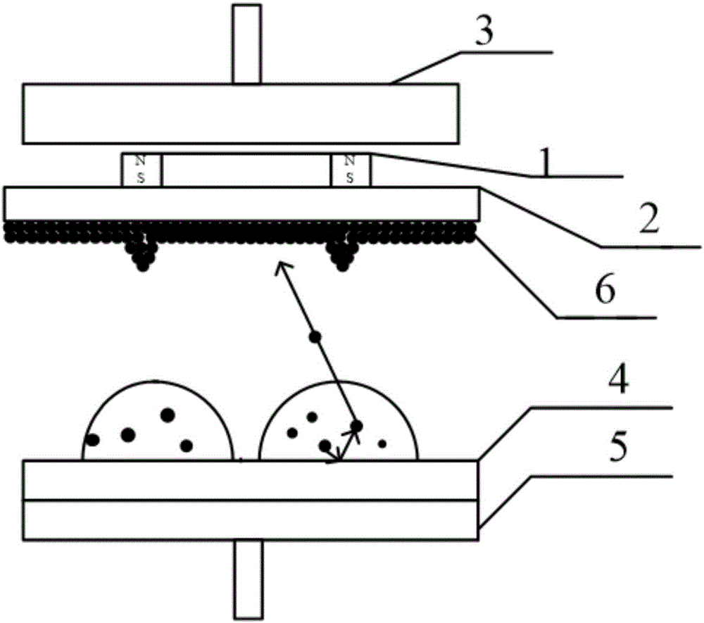
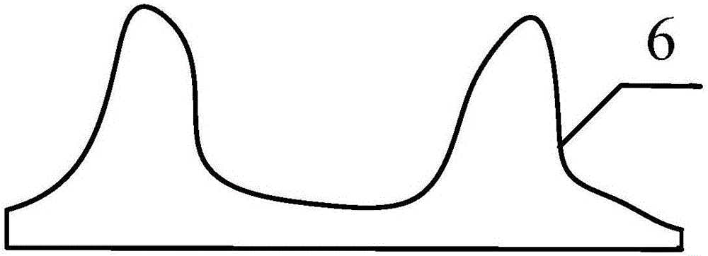
[0021] First use ANSYS finite element analysis to design and simulate the magnetic field, select the module, and determine the shape of the magnet as a ring magnet, the inner and outer diameters are 70mm and 80mm, the height of the magnet is 20mm, the magnetization of the ring magnet is 750kA / m, and the direction is along Z Axis positive. Except for the ring, the other areas are air. The boundary conditions were set, and the magnetic field distribution on the plane at a distance of 1.5 mm from the magnet was obtained after meshing; the magnetic field was constructed according to the magnetic field simulation results. Such as figure 1 As shown, select ring magnet 1 in the present embodiment, inner and outer diameters are respectively 70mm, 80mm, and magnet height is 10mm, and substrate is the quartz glass sheet 2 that surface flatness is less than 0.4nm, thickness 1.5mm, uses respectively acetone, ethanol, The substrates were ultrasonically cleaned with deionized water, and t...

Embodiment 2

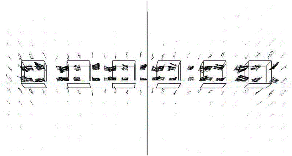
[0023] First use ANSYS finite element analysis to design and simulate the magnetic field, select the module, and determine that the shape of the magnet is a bar magnet. In this embodiment, the bar magnets with the same length, width and height are designed to be placed at equal intervals. The magnet is 10mm wide and 50mm high. The magnitude of the magnetization is 750kA / m, and the direction is along the positive direction of the Z axis. Except for the bars, the other areas are all air. Set the boundary conditions, and obtain the magnetic field distribution on the plane 1.5mm away from the magnet after meshing as image 3 shown; the magnetic field is constructed according to the magnetic field simulation results. Soft magnets have great toughness and high plasticity, and can be arbitrarily combined into desired graphics according to needs. In this example, for convenience of description, a bar magnet 8 with a simple magnetic field pattern is used. Place the strip-shaped sof...

Embodiment 3

[0025] First, use COMSOL finite element analysis to design and simulate the magnetic field, select the module, and determine that the shape of the magnet is cylindrical, with a diameter of 10mm and a height of 20mm. The arrangement of the three magnets is as follows Figure 5 As shown, the magnetization intensity is set to 750kA / m, and the direction is along the positive direction of the Z axis. Except cylinder 9, other areas are all air. After meshing, the magnetic field distribution on the plane at a distance of 1.5 mm from the magnet is obtained; the magnetic field is constructed according to the magnetic field simulation results. In this embodiment, three cylindrical magnets are selected to form a combined magnetic field that interferes with each other. Make sure that the bottom surface of the cylinder is on the same level and in close contact with the upper surface of the substrate, and then fix the placed magnet substrate on the positive sample stage of the magnetron sp...


PUM

PropertyMeasurementUnit
heightaaaaaaaaaa
heightaaaaaaaaaa
surface smoothnessaaaaaaaaaa

Abstract

The invention discloses a preparation method for a patterned film with a gradually changed thickness. The preparation method mainly comprises the following steps of: designing magnetic fields by utilizing software such as ANSYS and COMSOL according to a to-be-obtained pattern with a gradually changed thickness, wherein the magnetic fields consist of permanent magnets or soft magnets; then, fixing a substrate with the permanent magnets or the soft magnets onto a sample stage on a positive electrode of a magnetron sputtering apparatus, and enabling one surface, without a magnet, of the substrate to face towards a magnetic metal target; and fixing the magnetic metal target onto a target stage on a negative electrode of the magnetron sputtering apparatus, starting sputtering, observing reading of a film thickness meter in a sputtering process, stopping sputtering when the displayed film thickness reaches a proper thickness, thereby obtaining a metal film with a thickness in patterned distribution on the substrate. The method disclosed by the invention can be flexible and can obtain various patterned films, and the thicknesses of the films are in stepless gradual change; and meanwhile, the magnetic fields can be conveniently added into film preparation processes such as magnetic-control sputtering and vacuum heat deposition, magnets can be repeatedly used, and operations are flexible, so that the preparation method is simple and reliable, and is low in cost.

Description

technical field [0001] The invention belongs to the field of optical thin films, in particular to a preparation method for forming a patterned magnetic thin film with a gradient thickness. Background technique [0002] Gradient thickness films are an important part of optical films. Gradient thickness films can achieve continuous changes in parameters such as reflectivity, transmittance, and dispersion. For example, when the incident light moves along the direction of film thickness gradient, the transmitted light intensity also changes continuously. , which realizes the continuous attenuation of light. Gradient thickness films have important application value in light attenuation films, Fresnel lenses, two-dimensional optical components, etc. [0003] At present, most of the preparation methods for preparing Fresnel lenses and two-dimensional optical elements are photoetching methods of semiconductor preparation technology, that is, designing one or a group of masks with b...

Claims


Application Information

Patent Timeline
Patent Type & Authority Applications(China)
IPC IPC(8): C23C14/35C23C14/14C23C14/54
CPCC23C14/14C23C14/35C23C14/542
Inventor 刘雪强姜芳
Owner YANSHAN UNIV
Why Eureka
Try Eureka