Automatic adjustment photoelectric sensor signal circuit based on feedback system
A photoelectric sensor and automatic adjustment technology, applied in control/regulation systems, instruments, light control, etc., can solve problems such as measurement errors, difficult detection of pulse signals by sensors, and inability to self-adaptive measurement, etc., to achieve the effect of improving quality
- Summary
- Abstract
- Description
- Claims
- Application Information
AI Technical Summary
Problems solved by technology
Method used
Image
Examples
Embodiment 1
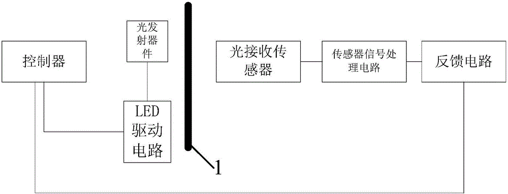
[0022] Such as figure 1 The shown a kind of automatically adjustable photoelectric sensor signal circuit based on the feedback system of the present invention includes a controller, an LED drive circuit, a light emitting device, a light receiving sensor, a sensor signal processing circuit and a feedback circuit, and the controller preferably A small control chip is used, but other controllers are also selected according to the size and function of the applicable instrument. The controller is connected with an LED drive circuit, and the LED drive circuit drives the light-emitting device to emit light. One of the light-emitting devices A light receiving sensor is arranged on the side, and a light blocking device 1 is arranged between the light emitting device and the light receiving sensor. After the light receiving sensor senses the light reflected from the affected part, the light blocking device 1 can effectively block the light emitting device from directly emitting The ligh...
Embodiment 2
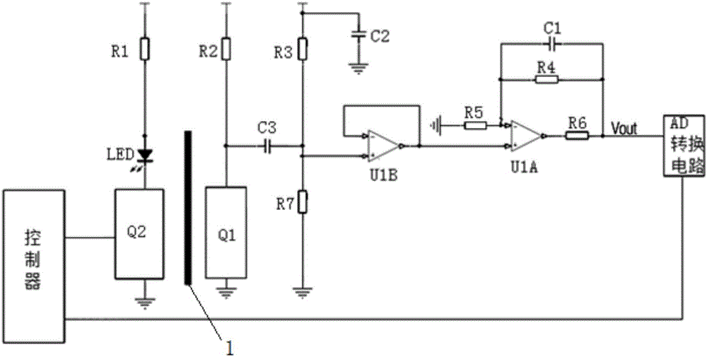
[0024] On the basis of the automatically adjustable photoelectric sensor signal circuit described in embodiment 1, as figure 2 As shown, the sensor signal processing circuit includes a switching resistor R2 connected to the light-receiving sensor Q1. After the light-receiving sensor Q1 receives the light signal reflected from the object to be measured, it will generate a photocurrent, and the photoelectric current will be transferred through the switching resistor R2. The light-receiving sensor Q1 is also connected to one end of the capacitor C3 that cuts off DC, and the other end of the capacitor C3 is connected to a DC bias circuit. After passing through the capacitor C3, the above-mentioned light-induced voltage retains the AC Component, filter out the DC component due to constant light, and then send it to the DC bias circuit. The light-induced AC component is superimposed by the DC bias voltage generated by the DC bias resistor to form a composite signal. This signal cont...
PUM
 Abstract
Description
Claims
Application Information
 - R&D
- Intellectual Property
- Life Sciences
- Materials
- Tech Scout
- Unparalleled Data Quality
- Higher Quality Content
- 60% Fewer Hallucinations
Browse by: Latest US Patents, China's latest patents, Technical Efficacy Thesaurus, Application Domain, Technology Topic, Popular Technical Reports.
© 2025 PatSnap. All rights reserved.Legal|Privacy policy|Modern Slavery Act Transparency Statement|Sitemap|About US| Contact US: help@patsnap.com


