Spherical electric vehicle magnetic suspension flywheel battery

A technology for electric vehicles and flywheel batteries, which is applied to electric vehicles, electric components, holding devices using magnetic attraction or thrust, etc., can solve the problems that limit the improvement of energy storage density and energy storage efficiency of flywheel batteries, the large size of flywheel batteries, and the maintenance of The problem of high cost, to achieve the effect of suppressing the gyro effect, improving the control accuracy, and large carrying capacity

Active Publication Date: 2017-04-26
JIANGSU UNIV
View PDF5 Cites 10 Cited by
  • Summary
  • Abstract
  • Description
  • Claims
  • Application Information

AI Technical Summary

Problems solved by technology

In addition, the generators / motors used in traditional flywheel batteries usually use permanent magnet motors or asynchronous motors. These conventional motors have the characteristics of low reliability in high-speed operation, high power consumption, and high maintenance costs during operation.
In addition, the flywheel battery installs the flywheel rotor, hybrid magnetic bearing and motor on the shaft as independent individuals. The hybrid magnetic bearing needs to provide the flywheel battery with 5 degrees of freedom controllable suspension support. Therefore, the flywheel battery is large in size, High cost, high energy consumption, and complex structure limit the improvement of the energy storage density and energy storage efficiency of flywheel batteries

Method used


Image

  • Spherical electric vehicle magnetic suspension flywheel battery
  • Spherical electric vehicle magnetic suspension flywheel battery
  • Spherical electric vehicle magnetic suspension flywheel battery

Examples


Embodiment Construction

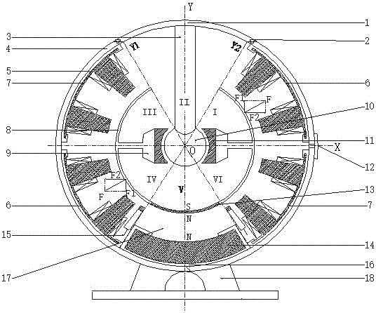
[0020] The present invention will be further explained below in conjunction with the accompanying drawings and specific embodiments. For the convenience of description, the Cartesian coordinate system XYO is set up, and the figure 1 The center of sphere O of middle ball crown flywheel housing 4 is determined as origin. Place the vertical vertical cross-sectional structure in the middle of the flywheel battery of the present invention in the Cartesian coordinate system XYO, and divide the vertical longitudinal cross-sectional structure into six equal parts along the circumferential direction in the Cartesian coordinate system XYO with the origin O as the center. The radian occupied by the part is 60 degrees, so that the flywheel housing 4 forms six areas, which are called I, II, III, IV, V, and VI areas.

[0021] see figure 1 Shown, the outside of the present invention is a support frame 18 and a spherical crown flywheel casing 4, and the bottom end of the spherical crown fly...


PUM


Abstract

The invention discloses a spherical electric vehicle magnetic suspension flywheel battery; an inner housing, a spherical stator, a spherical cavity rotor, two permanent magnets and two magnetic suspension spherical surface bearings are arranged in a vacuum cavity; the spherical stator is arranged in the right center of the flywheel housing; the spherical cavity rotor is arranged outside the spherical stator; the spherical cap shape inner housing having the same spherical core is arranged outside the spherical cavity rotor; the bottom opening of the inner housing is seamlessly fixedly connected with the first permanent magnet in a spherical cap shape; the inner housing and the spherical cavity rotor are fixedly connected through a rotor connector; the second permanent magnet in the spherical cap shape is arranged right below the first permanent magnet, and fixedly connected on the inner surface of the flywheel housing; the two magnetic suspension spherical surface bearings are arranged between the flywheel housing and the inner housing, fixedly connected on the inner wall of the flywheel housing, and two central shafts thereof are intersected. The spherical electric vehicle magnetic suspension flywheel battery can eliminate air friction losses on the flywheel, and can increase the gyro control moment scope, thus inhibiting the flywheel gyroscopic effect.

Description

technical field [0001] The invention relates to the structure of a flywheel battery (also called a flywheel energy storage device), in particular to a magnetic levitation flywheel battery for electric vehicles. Background technique [0002] A flywheel battery is a new type of mechanical energy storage device that uses a high-speed rotating flywheel to store energy in the form of kinetic energy. Compared with existing chemical batteries, flywheel batteries have many advantages such as high energy storage density, long service life, high energy conversion efficiency, no pollution, and short charging time. At present, flywheel batteries are widely used in electric vehicles, aerospace, uninterruptible power supply (UPS) and other fields. [0003] The gyro effect caused by the high-speed rotating flywheel battery rotor encountering external interference is a technical problem restricting the development of flywheel batteries. This problem is mainly reflected in the topology of t...

Claims


Application Information

Patent Timeline
Patent Type & Authority Applications(China)
IPC IPC(8): H02K7/02H02N15/00
CPCH02K7/025H02N15/00Y02E60/16Y02T10/64
Inventor 张维煜杨恒坤朱熀秋陈涛
Owner JIANGSU UNIV
Why Eureka
Try Eureka