
A kind of vacuum tower internals with cross-flow tray defoaming and two-way spraying for heat extraction

A technology of decompression tower and flow tray, applied in fractional distillation, vacuum distillation, separation method, etc., can solve the problems of difficult realization of engineering, reduction of heat transfer height of empty tower, and increase of operating cost.

Active Publication Date: 2018-11-02
CHINA UNIV OF PETROLEUM (EAST CHINA)
View PDF6 Cites 0 Cited by
  • Summary
  • Abstract
  • Description
  • Claims
  • Application Information

AI Technical Summary

Problems solved by technology

[0005] Due to the confidentiality of foreign technologies, domestic research on spray systems and contact heat transfer has not made breakthroughs in empty tower heat transfer technology for many years. The height of the empty tower section always needs to be more than 6m, and some working conditions need to reach the requirement of 12m. Engineering is very difficult. Difficult to achieve
Later, through the research on the direct contact heat transfer efficiency and the influence of empty tower kinetic energy factor on the droplet entrainment of atomizing nozzle, the heat transfer height of the empty tower was greatly reduced, which reached the possibility of engineering realization. The two-stage heat transfer section The pressure drop of the packing is greatly reduced, which is beneficial to the decompression and deep drawing; but the consequences are that the tower diameter becomes larger, the reflux flow increases, and the thermal quality of the reflux temperature decreases. The investment in recovery and other aspects and the operating cost of the pump will increase. Although two sections of packing are reduced in the tower internal components, the investment in other internal components will increase correspondingly due to the increase in shell diameter.
[0006] In addition, as the crude oil becomes heavier and inferior, the acidity increases, and the corrosion of the internal parts of the atmospheric and vacuum tower becomes more and more serious. The packing is too thin and the corrosion allowance is insufficient. It is urgent to develop a low-pressure drop high-efficiency vacuum tray

Method used


Image

  • A kind of vacuum tower internals with cross-flow tray defoaming and two-way spraying for heat extraction

Examples


Embodiment

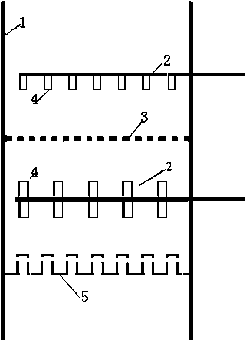
[0018] A decompression tower internal part with two-way spray heat extraction with cross-flow tray defoaming is integrated through the following structure: each heat extraction section is provided with two layers of dendritic jet liquid distributors (2), and the upper layer The atomizing nozzle (4) of the liquid distributor (2) sprays downward, and the lower liquid distributor (2) is provided with two groups of atomizing nozzles (4) upward and downward; the atomizing liquid of the upper liquid distributor (2) The droplets are relatively large, and the mist entrainment rate of the airflow is less than 10%; the atomized droplets of the lower liquid distributor (2) are finer, which enhances heat transfer, and are sprayed to the through-flow sieve tray (3) for coalescence and recovery; two layers of tree branches A layer of through-flow sieve trays (3) are installed between the jet-shaped liquid distributors (2), the plate surface opening ratio is 30-60%, and the hole diameter is 3...


PUM


Abstract

The invention relates to a two-way spray heat-removing vacuum tower inner part provided with a dual-flow tray for despumating. Two layers of branch-shaped jet type liquid distributors are arranged on each heat removing section, wherein an atomization nozzle of the liquid distributor arranged at the upper layer sprays downwards, and the liquid distributor arranged at the lower layer is provided with two groups of atomization nozzles which respectively spray upwards and downwards; one layer of dual-flow sieve tray is installed between the two layers of branch-shaped jet type liquid distributors; the distances between the liquid distributors and the dual-flow sieve tray is spray distances from atomizer cones of the atomization nozzles at the outmost circles of the liquid distributors to the wall of the tower; an oil collecting tank is installed under the liquid distributor arranged at the lower layer, and the distance between the oil collecting tank and the liquid distributor is greater than 600mm.

Description

1. Technical field [0001] The invention provides an internal part of a vacuum tower with a two-way spray heat-taking heat-taking device with cross-flow tray defoaming, and relates to the field of petroleum refining. 2. Background technology [0002] Atmospheric and vacuum distillation units are the leading equipment in refineries and the basic equipment for deep processing, which directly affects the comprehensive benefits of the entire refinery. [0003] With the heavy and inferior quality of crude oil and the large-scale production of unconventional heavy and inferior oil such as shale oil, oil sand oil, heavy (thick) oil, super heavy oil, deep oil, asphalt, and coal tar in the future, it is difficult to directly As raw material for catalytic cracking of heavy oil. Improve the decompression extraction rate, strive to produce more catalytic cracking or hydrocracking raw materials, and reduce the yield of residual oil. It is the refining enterprise's overall plan to optimiz...

Claims


Application Information

Patent Timeline
Patent Type & Authority Patents(China)
IPC IPC(8): B01D3/14B01D3/10B01D3/22
CPCB01D3/10B01D3/105B01D3/106B01D3/14B01D3/225B01D3/42
Inventor 田原宇乔英云田斌
Owner CHINA UNIV OF PETROLEUM (EAST CHINA)
Learn More