Eureka AIR delivers breakthrough ideas for toughest innovation challenges, trusted by R&D personnel around the world.

An integral casting mold for an aero-engine diffuser

An aero-engine and integral casting technology, which is applied in the field of aero-engines, can solve problems such as error-prone, large mold bottom plate size, and low part qualification rate, so as to strengthen the anti-deformation effect, avoid deformation, and improve casting precision and production efficiency Effect

Active Publication Date: 2018-11-02
AECC AVIATION POWER CO LTD
View PDF9 Cites 0 Cited by
  • Summary
  • Abstract
  • Description
  • Claims
  • Application Information

AI Technical Summary

Problems solved by technology

However, due to thin wall thickness and bonding operation error, it is easy to cause the shape and size of the parts not to meet the requirements, and it is easy to have wrong shapes, the qualified rate of parts is low, and the molding efficiency is low.
[0005] However, the overall one-time molding of the diffuser mainly has the following difficult problems. At present, there is no corresponding mold that can solve these problems: to ensure the final size of the part channel and prevent deformation during the molding process; to ensure the shape of the inner wall of the part’s inner ring. And the final size at the same time to prevent the deformation problem in the forming process; the reverse draft feature formed by the outer ring support plate and the outer edge plate is difficult to form, because the angle formed by the extension direction of the outer ring support plate and the outer edge plate is less than 90°, forming an inverted Drafting phenomenon; the ejection problem of parts with ring structure and thin-walled features in the mold, it is necessary to eject the wax pattern smoothly without deformation or damage to make the mold operation smooth; multiple groups of splicing inserts and mold bottom plate The problem of large size and complex shape has caused great difficulties in the processing of molds and fitter assembly

Method used


Image

  • An integral casting mold for an aero-engine diffuser
  • An integral casting mold for an aero-engine diffuser
  • An integral casting mold for an aero-engine diffuser

Examples


Embodiment Construction

[0035] The present invention is described in further detail below in conjunction with accompanying drawing:

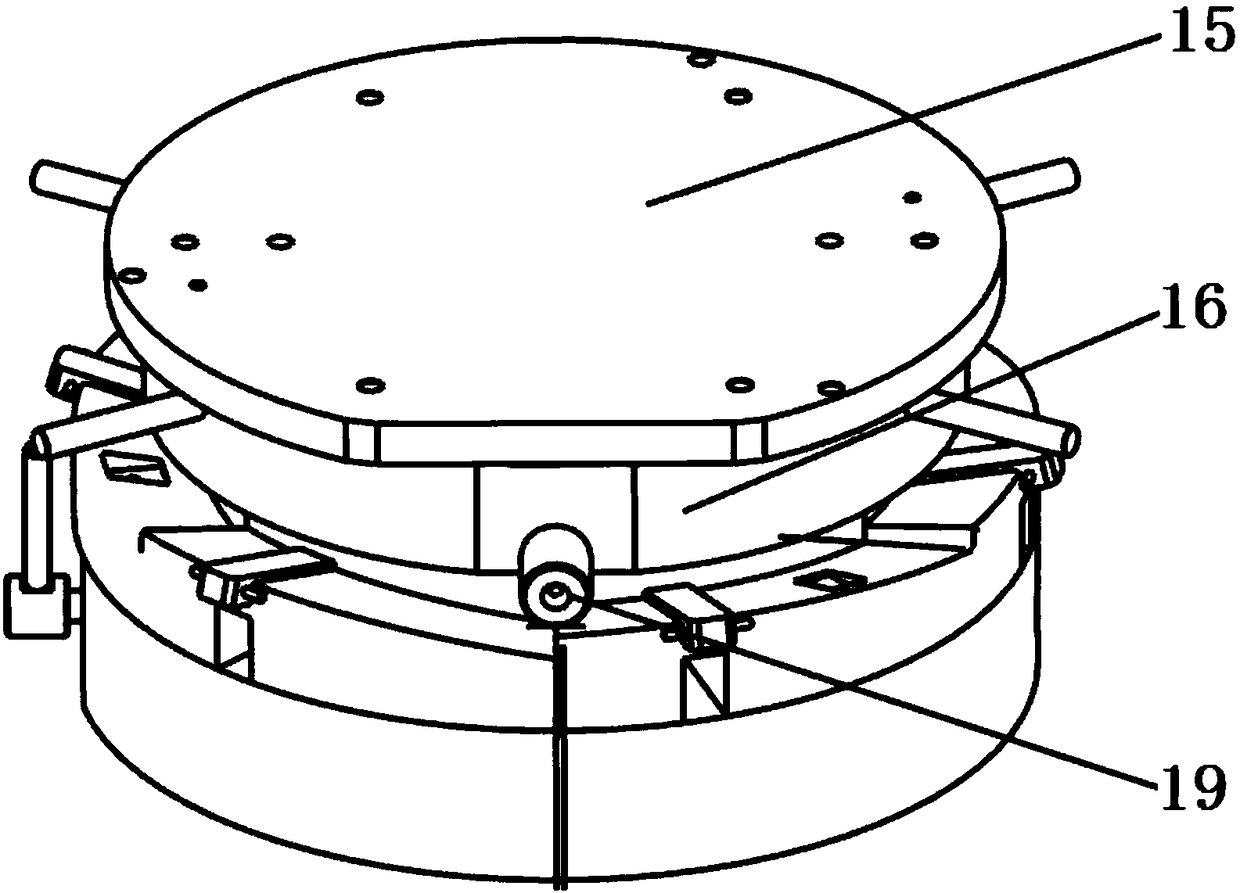
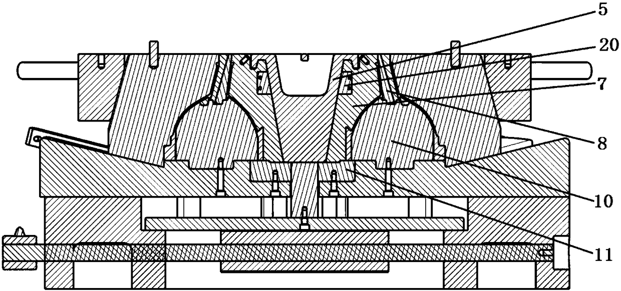
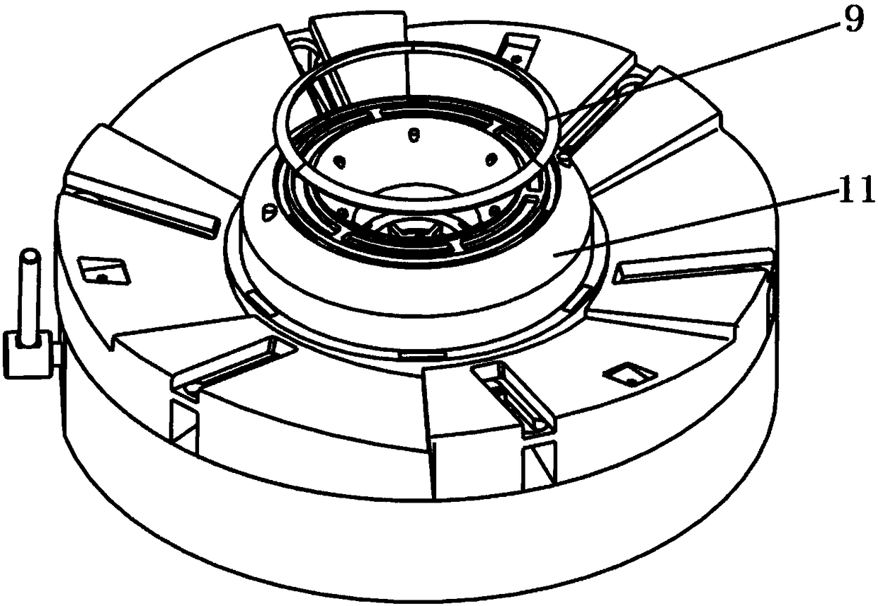
[0036] The invention provides an integral casting mold for an aero-engine diffuser, such as Figure 1-6 As shown, including the base 1, an inner annular cavity structure is provided between the base 1 and the upper cover plate 15, and the inner annular cavity structure communicates with the wax injection nozzle 19, and the wax injection nozzle 19 is used for Wax injection is performed in the annular inner cavity; the inner ring cavity structure is composed of several cavity parts, the cavity parts include the inner ring fixing block 10, the bottom of the inner ring fixing block 10 is provided with an outer ring fixing block 11 for fixing its position, The outer side of the inner ring fixed block 10 is provided with a movable block 7, and the top of the inner ring fixed block 10 is provided with a blade body movable block group 8; as image 3 As shown, a follow-up mova...


PUM


Abstract

The invention discloses an integrally casting mold for an aero-engine diffuser. The mold comprises a pedestal and an upper cover plate, wherein an inner ring-shaped cavity structure of the diffuser is integrally formed between the pedestal and the upper cover plate, a frustum cone-shaped loose core is arranged at the center position of the inner ring-shaped cavity structure, a wax injection nozzle communicating with the inner ring-shaped cavity is arranged on the inner ring-shaped cavity structure; and an ejection structure for ejecting the molded diffuser is arranged at the bottom of the inner ring-shaped cavity structure. According to the mold provided by the invention, the diffuser cast can be integrally formed into a ring at a time without subsequent wax molding adhesion, and the problem of reverse pulling of the wax on the mold can be solved, and forming of the aero-engine diffuser with the thick wall is ensured.

Description

technical field [0001] The invention belongs to the technical field of aero-engines, and relates to a casting device for an aero-engine diffuser, in particular to an integral casting mold for an aero-engine diffuser Background technique [0002] Diffuser is one of the important components of aero-engine and gas turbine, located between the compressor and the main combustion chamber, used to convert the kinetic energy of the high-speed air exiting the compressor impeller into pressure energy, and then transport the gas with pressure energy to The main combustion chamber is supercharged and heated to the allowable temperature in front of the turbine so that it can enter the exhaust device to do work. The pressure energy is one of the important indicators to measure the performance of the engine. [0003] At present, the world's advanced annular diffuser, in view of the dual reasons of reducing weight and ensuring the structural stability of parts, mostly uses hollow support pl...

Claims


Application Information

Patent Timeline
Patent Type & Authority Patents(China)
IPC IPC(8): B22C7/02
CPCB22C7/02
Inventor 杨成李鹏程刚王卫东袁强郭庆芳李杨阳祁俊玮
Owner AECC AVIATION POWER CO LTD
Why Eureka
Eureka Blog
Learn More