

Vertical type direct connection draught fan
A direct-connected, vertical technology, used in electromechanical devices, mechanical equipment, non-variable-capacity pumps, etc., can solve the problems of low speed, low efficiency, and low pressure ratio of the prime mover motor, and achieve low starting current, fewer components, The effect of increasing the magnetic flux density
- Summary
- Abstract
- Description
- Claims
- Application Information
AI Technical Summary
Problems solved by technology
Method used
Image

Examples
Embodiment 1
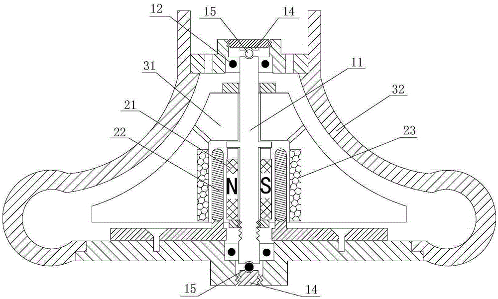
[0033] Embodiment 1 The permanent magnet rotors are distributed axially, and the fans are arranged vertically.
[0034] see figure 1 , the permanent magnet rotor 21 and the stator coil 22 are distributed axially, the permanent magnets of the permanent magnet rotor are arranged around the axis in the axial direction of the shaft, and the stator coils corresponding to the permanent magnet rotor are also arranged around the axis in the axial direction of the shaft , that is, both the permanent magnet rotor and the stator coil are cylindrical; a magnetizer cylinder 23 is arranged on the outside of the stator coil symmetrical to the permanent magnet rotor, and the permanent magnet rotor 21, the stator coil 22 and the magnetizer cylinder 23 are placed on the body of the impeller 31 In the cavity of the impeller, the magnetic conductor cylinder 23 is fixedly connected with the impeller body and rotates with the shaft. And the positions of the permanent magnet rotor 21 and the magnet...
Embodiment 2
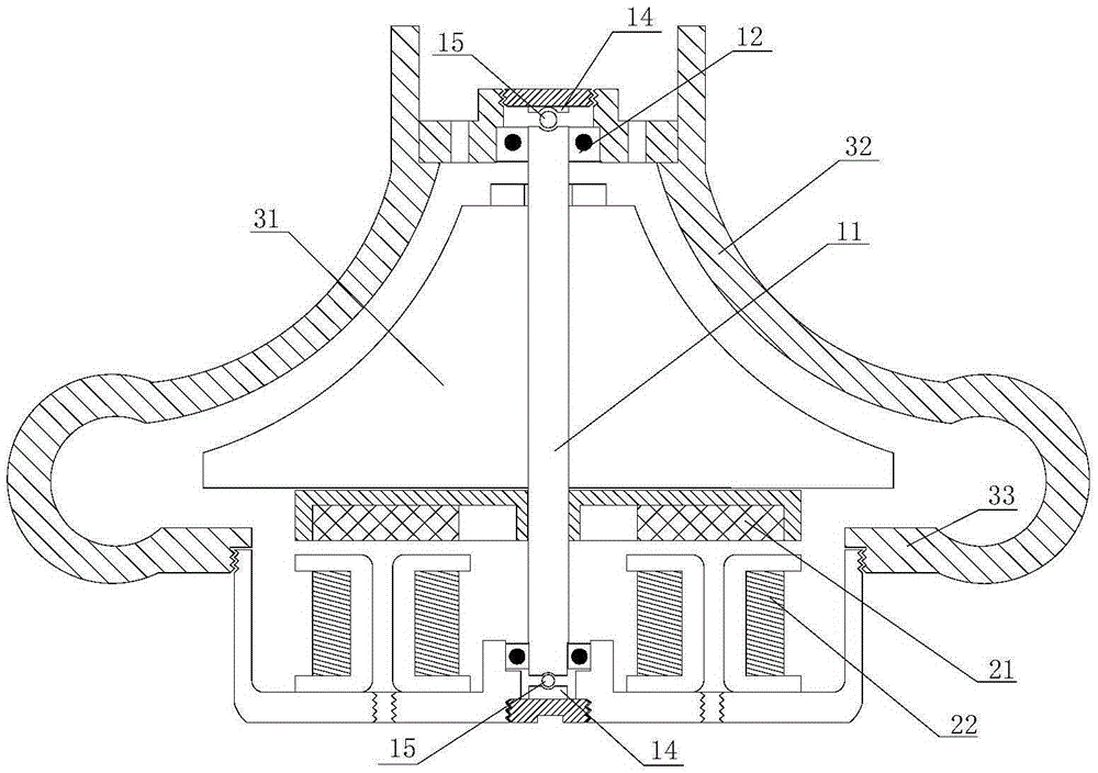
[0038] Embodiment 2 The permanent magnet rotors are radially distributed, and this embodiment is vertically arranged.
[0039] see figure 2 , the basic structure of the impeller, shaft and impeller shell is similar to that of Embodiment 1, the special feature is that the permanent magnet rotors are radially distributed, the permanent magnet rotors are arranged according to the radial distribution of the shaft, the permanent magnet rotors are disc-shaped, and the permanent magnet rotor discs after the impeller. The corresponding stator coils are concentrated windings, which are also distributed around the shaft in the radial direction of the shaft. This structure is suitable for fans with high torque and slightly low speed.
[0040] Experimental results show that the rotational speed can reach above 15000rpm. The wind pressure ratio can reach more than 1.5.
Embodiment 3
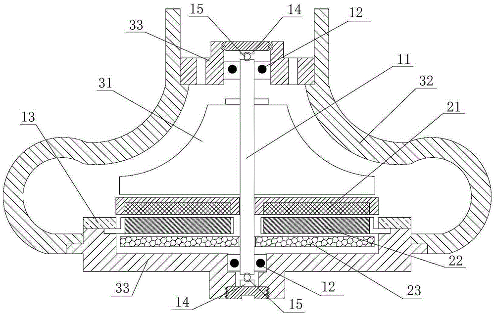
[0042] see image 3, the basic structure is similar to that of Embodiment 2, and the special feature is that the stator coil is also in the shape of a flat disk, and a magnetizer disk 23 is arranged on the other side of the stator coil symmetrical to the permanent magnet rotor, and the magnetizer disk is fixed to the shaft Connected, the stator coil 22 is interposed between the permanent magnet rotor 21 and the magnetizer disk 23; a radial guide vane 13 is installed on the rear side of the impeller, and the guide vane is fixed to the impeller shell through the rear plate 33.
[0043] The stator coil is also in the shape of a flat disk, so as to increase the torque and reduce the axial distance so that the shafting works in a rigid state, reduce the critical effect and increase the torque.
PUM
 Abstract
Description
Claims
Application Information