Eureka AIR delivers breakthrough ideas for toughest innovation challenges, trusted by R&D personnel around the world.

Durable driving belt

A kind of transmission belt, durable technology, applied in the direction of transmission belt, belt/chain/gear, conjugated rayon, etc., can solve the problem of poor ventilation, wear resistance, heat and aging resistance of the pressing surface of the transmission belt, and the transmission belt is prone to peeling. and other problems, to achieve good adhesion, prolong service life, and improve ventilation and ventilation performance.

Active Publication Date: 2017-05-10
日照新睿招商发展有限公司
View PDF6 Cites 8 Cited by
  • Summary
  • Abstract
  • Description
  • Claims
  • Application Information

AI Technical Summary

Problems solved by technology

[0003] The transmission belt will inevitably produce mechanical actions such as twisting, pulling and friction during the transmission process, which will cause the transmission belt to be easily worn. In order to improve the strength of the transmission belt and prolong the service life of the transmission belt, it is necessary to improve the wear resistance, durability and Start with heat resistance
The raw materials of transmission belts have been developed from natural rubber to synthetic rubber. The existing synthetic rubber for making transmission belts has poor wear resistance, heat resistance, and aging resistance, and their mechanical strength is not high enough. In order to blindly improve their mechanical strength, some developed synthetic rubbers The flexible shape of the synthetic rubber is reduced, so that the compressed transmission belt is prone to peeling between the jump layers; on the other hand, the pressing surface of the transmission belt has poor ventilation, so that the heat generated by the friction between the transmission belt and the transmission wheel is not easy. Dissipate, accelerate the wear of the transmission belt, and bring safety hazards to the electromechanical equipment

Method used


Image

  • Durable driving belt
  • Durable driving belt
  • Durable driving belt

Examples


Embodiment 1

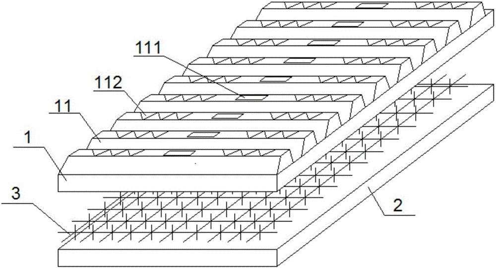
[0037] Such as Figure 1~3 As shown, the present invention provides a durable power transmission belt, which includes a compression rubber layer 1 that is crimped with a power transmission component, an adhesive rubber layer 2 bonded to the compression rubber layer 1, and a rubber layer 2 disposed on the compression rubber layer 1 and the reinforcing layer 3 between the bonding rubber layer 2,

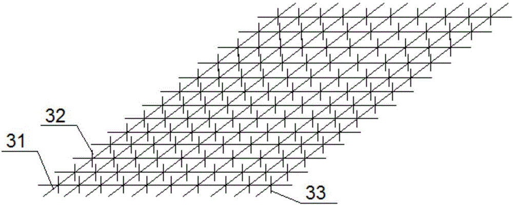
[0038] Wherein, the reinforcement layer 3 includes a composite fiber web 31 laying flat between the compression rubber layer 1 and the bonding rubber layer 2 , and a fiber web that can extend into the first surface of the composite fiber web 31 . A plurality of first bonding rods 32 inside the compressed rubber layer 1, a plurality of second bonding rods arranged on the second surface of the composite fiber web 31 and capable of extending into the inside of the bonding rubber layer 2 33 and the reinforcing cotton filled inside the grid of the composite fiber net 31, the reinforcing co...

Embodiment 2

[0055] Such as Figure 1~3 As shown, the present invention provides a durable power transmission belt, which includes a compression rubber layer 1 that is crimped with a power transmission component, an adhesive rubber layer 2 bonded to the compression rubber layer 1, and a rubber layer 2 disposed on the compression rubber layer 1 and the reinforcing layer 3 between the bonding rubber layer 2,

[0056] Wherein, the reinforcement layer 3 includes a composite fiber web 31 laying flat between the compression rubber layer 1 and the bonding rubber layer 2 , and a fiber web that can extend into the first surface of the composite fiber web 31 . A plurality of first bonding rods 32 inside the compressed rubber layer 1, a plurality of second bonding rods arranged on the second surface of the composite fiber web 31 and capable of extending into the inside of the bonding rubber layer 2 33 and the reinforcing cotton filled inside the grid of the composite fiber net 31, the reinforcing co...

Embodiment 3

[0073] Such as Figure 1~3 As shown, the present invention provides a durable power transmission belt, which includes a compression rubber layer 1 that is crimped with a power transmission component, an adhesive rubber layer 2 bonded to the compression rubber layer 1, and a rubber layer 2 disposed on the compression rubber layer 1 and the reinforcing layer 3 between the bonding rubber layer 2,

[0074] Wherein, the reinforcement layer 3 includes a composite fiber web 31 laying flat between the compression rubber layer 1 and the bonding rubber layer 2 , and a fiber web that can extend into the first surface of the composite fiber web 31 . A plurality of first bonding rods 32 inside the compressed rubber layer 1, a plurality of second bonding rods arranged on the second surface of the composite fiber web 31 and capable of extending into the inside of the bonding rubber layer 2 33 and the reinforcing cotton filled inside the grid of the composite fiber net 31, the reinforcing co...


PUM


Abstract

The invention discloses a durable driving belt comprising a compressing rubber layer, a bonding rubber layer and a strengthening layer. The compressing rubber layer is connected with a power transmission assembly in a pressing mode, the bonding rubber layer bonds with the compressing rubber layer, and the strengthening layer is arranged between the compressing rubber layer and the bonding rubber layer, wherein the strengthening layer comprises composite fiber webs, first bonding rods, second bonding rods and strengthening cotton. The composite fiber webs are obtained by multiple fiber spinning solutions through the electrospinning technique. The first bonding rods and the second bonding rods are all obtained by smearing bonder on the outer portion of a plastic pipe. The driving belt has higher mechanical strength, flexibility is good, the abrasion resistance and heat resistance properties are excellent, the service life of the driving belt is greatly prolonged, and driving efficiency of the driving belt can be greatly improved.

Description

technical field [0001] The invention relates to mechanical transmissions. More specifically, the present invention relates to a durable power transmission belt. Background technique [0002] The transmission belt is the core connecting part of the power transmission of the electromechanical equipment. It mainly transmits the power of the power source to the mechanical equipment by being sleeved on the transmission wheel. There are many kinds of transmission belts and their uses are extremely wide, ranging from giant motors of several thousand kilowatts to micro motors of less than one kilowatt, and even precision machinery such as home appliances, computers, and robots are inseparable from transmission belts. [0003] The transmission belt will inevitably produce mechanical actions such as twisting, pulling and friction during the transmission process, which will cause the transmission belt to be easily worn. In order to improve the strength of the transmission belt and pro...

Claims


Application Information

Patent Timeline
IPC IPC(8): F16G1/28F16G1/21D01F8/18D01F8/12C09J123/08C09J11/04C09J11/06C09J11/08C09J4/06C08L33/04C08L9/00C08K13/04C08K3/36C08K7/24C08K3/04C08K3/38
CPCC08K2201/014C08L33/04C08L2205/035C09J4/06C09J11/04C09J11/06C09J11/08C09J123/0853D01F8/12D01F8/18F16G1/08F16G1/21F16G1/28C08K13/02C08K5/103C08K5/12C08K3/346C08L9/00C08K13/04C08K3/36C08K7/24C08K3/04C08K3/38
Inventor 刘钰馨
Owner 日照新睿招商发展有限公司
Why Eureka
Eureka Blog
Learn More