Gas burner capable of producing ionized gas flame

A gas burner and burner technology, which is applied in the directions of gas fuel burners, burners, combustion types, etc., to achieve the effects of uniform proportioning, reduction of exhaust emissions, and uniform splitting of gas molecules

Inactive Publication Date: 2017-05-10
伍镜清
View PDF7 Cites 0 Cited by
  • Summary
  • Abstract
  • Description
  • Claims
  • Application Information

AI Technical Summary

Problems solved by technology

[0005] The purpose of the present invention is to improve a gas burner that can generate ionized gas flames in order to solve the above-mentioned shortcomings of the existing burner.

Method used


Image

  • Gas burner capable of producing ionized gas flame
  • Gas burner capable of producing ionized gas flame
  • Gas burner capable of producing ionized gas flame

Examples


Embodiment 1

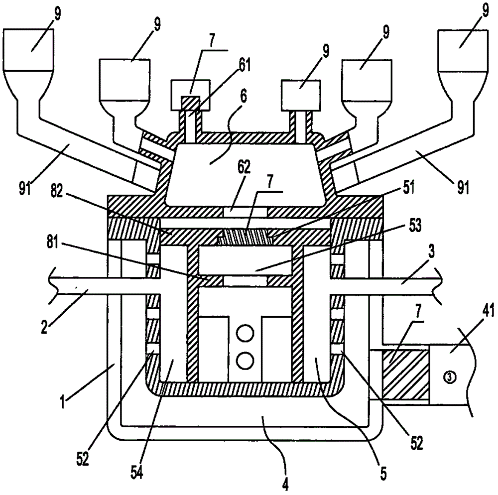
[0035] Such as Figure 1 to Figure 3 A gas burner that can generate ionized gas flames is shown, including a burner body 1, an air input channel 2, and a gas input channel 3, and the burner body 1 includes a fresh air chamber 4 and an air mixing chamber 5 and the confluence chamber 6, the air mixing chamber 5 is arranged in the fresh air chamber 4, and there is a gap 7 acting on the air channel between the air mixing chamber 5 and the fresh air chamber 4, and the confluence chamber 6 is arranged in the air mixing chamber 5 The upper part communicates with the gas mixing chamber 5 to form a sealed burner body 1; the air input channel 2 and the gas input channel 3 are arranged in the middle of the gas mixing chamber 5, and the fresh air inlet 41, The air mixing outlet 51 of the air mixing chamber 5 and the air outlet 61 of the confluence chamber 6 are respectively provided with a swirl compressor 7 .

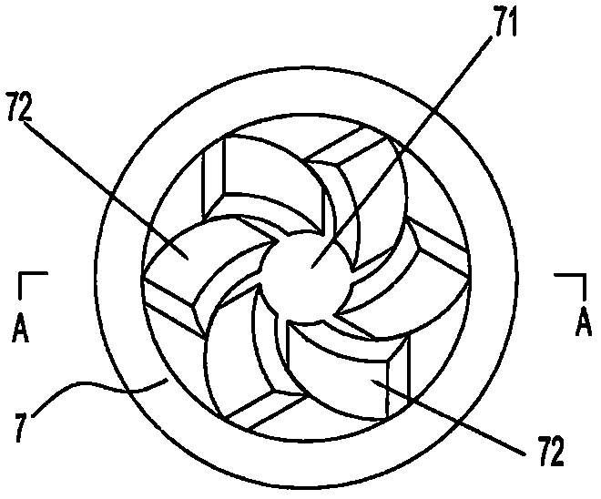
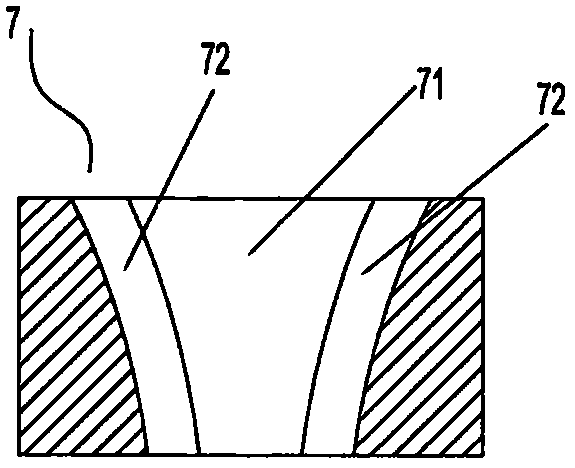
[0036] Further, the swirl compressor 7 is composed of a ventilation part wit...

Embodiment 2

[0041] The technical characteristics of this embodiment are: as Figure 4 As shown, a plurality of second air inlet holes 55 are also provided on the catalytic converter 8, and the second air inlet holes 55 correspond to the first air inlet holes 52, forming a straight passage of gas. The confluence inlet 62 of the confluence chamber 6 is a through hole located directly above the gas mixing outlet 51 of the gas mixing chamber 5, and a certain distance is reserved between the confluence inlet 62 and the gas mixing outlet 51, so that the connection between the confluence chamber 6 and the catalytic converter 8 An inner chamber 85 is formed between the upper cover plates 82 , and a confluence inlet 86 is provided at the confluence inlet 62 . The size of the confluence inlet 86 corresponds to the size of the inner chamber 53 of the gas mixing chamber 5 . The upper cover plate 82 of the catalytic converter 8 is located above the air gap 54 and is provided with a plurality of catal...

Embodiment 3

[0043] The technical characteristics of this embodiment are: as Figure 5 As shown, the confluence chamber 6 is provided with an installation base plate 63 corresponding to the gas mixing chamber 5, and the confluence chamber 6 is installed on the fresh air chamber 4 and the gas mixing chamber 5 through the installation base plate 63, in a vertical distribution structure, so that The fresh air chamber 4, the mixed air chamber 5 and the confluence chamber 6 form a burner housing in a closed mode, and the confluence inlet 86 is arranged below the installation base plate 63, and one or more convection currents are provided on the installation base plate 63. The hole 631, the convection hole 631 is located on the outside of the confluence inlet 86 corresponding to the convection flow 821 of the catalytic converter, and the rest is the same as the above embodiment.


PUM


Abstract

The invention discloses a gas burner capable of producing ionized gas flame and relates to a gas burn device with energy saving, efficient and environmentally friendly functions. The gas burner comprises a burner main body (1), an air input channel (2) and a gas input channel (3) and is characterized in that the burner main body (1) comprises a fresh air room (4), a mixed gas room (5) and a conflux room (6). The mixed gas (5) room is arranged in the fresh air room (4). An interval (7) used for an air channel is reserved between the fresh air room (4) and the mixed gas room (5). The conflux room (6) is arranged on the mixed gas room (5) and communicates with the mixed gas room (5), and the sealed burner main body (1). Rotational compressors (7) are arranged at a fresh air inlet (41) of the fresh air room (4), a mixed gas outlet (51) of the mixed gas room (5) and an air outlet (61) of the conflux room (6) correspondingly. According to the gas burner capable of producing the ionized gas flame, gas molecules can be fully split into ionized gas, proportion coordination among ionized gas molecules is more uniform, and the ionized gas molecules are fully burned. Therefore, waste gas emission is reduced, and the burning rate of the gas is increased.

Description

technical field [0001] The invention relates to a combustion equipment used in industries such as industry, canteens, and power plants, and in particular to an energy-saving, high-efficiency, and environment-friendly gas combustion device. Background technique [0002] The traditional burner is a device that properly mixes fuel and air to make the fuel ignite and burn stably. For a long time, people have been constantly pursuing the research and exploration of improving the perfect combustion quality standard without interruption. Perfect thermal efficiency refers to the calorific value unit contained in the fuel. The calorific value released after the burner does work is the ratio of the calorific value absorbed by the heated body. The highest heat absorption rate and the least heat loss are the most ideal. [0003] Therefore, in order to pursue higher combustion efficiency, all kinds of gas burners, whether for civil or industrial use, are constantly being introduced, and...

Claims


Application Information

Patent Timeline
IPC IPC(8): F23D14/02F23D14/18F23D14/58F23D14/64F23D14/70
CPCF23D14/02F23D14/18F23D14/58F23D14/64F23D14/70
Inventor 伍镜清
Owner 伍镜清
Why Eureka
Try Eureka