Center furnace liner L-shaped guide pipe vertical gas boiler

A gas-fired boiler and vertical boiler technology, applied in the direction of fixed conduit components, fluid heaters, heat exchangers, etc., can solve the problems of low fluid convective heat transfer coefficient, short flue gas flow, low water circulation rate, etc., to achieve enhanced The effect of natural convection heat transfer, increasing the radiation heat transfer area, and expanding the heating area

Inactive Publication Date: 2017-05-10
ZHENGZHOU UNIV
View PDF6 Cites 2 Cited by
  • Summary
  • Abstract
  • Description
  • Claims
  • Application Information

AI Technical Summary

Problems solved by technology

[0002] The furnace of the vertical hot water boilers available on the market today is generally set at the lower part of the boiler, the furnace space is relatively narrow, the gas emitted by the burner is limited by the space of the furnace, the shape of the flame cannot be fully expanded, and the combustion is insufficient. The gas is discharged before it is completely burned, and the heat energy loss is relatively large
The internal water circulation mode of the boiler is natural convection, the heat transfer area is small, and th

Method used


Image

  • Center furnace liner L-shaped guide pipe vertical gas boiler
  • Center furnace liner L-shaped guide pipe vertical gas boiler

Examples


Embodiment Construction

[0013] The present invention will be further described below in conjunction with the accompanying drawings.

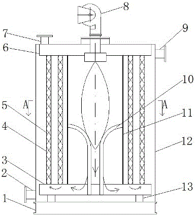
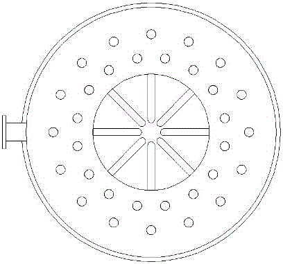
[0014] The cylinder of the central furnace L-shaped duct vertical gas boiler is equipped with a smoke collection box, a smoke transfer chamber, a furnace and a smoke pipe. The furnace is equipped with an L-shaped duct that is radial in the center. When installing, first put the furnace It is welded vertically with the upper smoke collecting box and the lower smoke transfer chamber, and then the L-shaped pipe is put in from the upper part of the furnace, and its upper end is welded with the hole in the middle wall of the furnace, and the lower end is welded with the bottom plate of the smoke transfer chamber; the smoke pipe The two ends are respectively welded on the annular tube plate of the smoke collection box and the smoke transfer chamber, and the steel sheet is twisted to make a spiral deflector, and placed in the smoke tube; the burner is fixed on the top of the v...


PUM


Abstract

The invention discloses a center furnace liner L-shaped guide pipe vertical gas boiler. The center furnace liner L-shaped guide pipe vertical gas boiler comprises a combustor, a cylinder, a furnace liner, L-shaped guide pipes, smoke collecting boxes, smoke pipes, a spiral guide piece, smoke transfer chambers, a water inlet pipe, a water outlet pipe, a smoke discharge pipe, a support pipe and a base, and is characterized in that the combustor is positioned at the top end of the vertical boiler cylinder; the furnace liner is positioned in the center position of the vertical boiler; multiple L-shaped guide pipes are arranged in the furnace liner, and form a center radial shape; the upper ends of the L-shaped guide pipes penetrate through the wall surface of the middle part of the furnace liner to weld with the wall surface, and the lower ends penetrate through a baseplate of the smoke transfer chamber to weld with the baseplate; the smoke pipes are arranged around the furnace liner; the smoke collecting boxes are respectively connected to the upper ends of the smoke pipes and the furnace liner; and the smoke transfer chambers are respectively connected to the lower ends of the smoke pipes and the furnace liner. Smoke radially exchanges heat with the furnace liner and the L-shaped guide rails to increase the radial heat exchange area; and furnace water in the L-shaped guide pipes is heated to quickly flow upwards, so that the natural convection heat exchange of the furnace water is reinforced, and the circulation of water in the furnace is quickened. The boiler is compact in structure, larger in heat exchange area and higher in heat efficiency.

Description

technical field [0001] The invention relates to a vertical gas boiler, in particular to a vertical gas boiler with an L-shaped duct in a central furnace. Background technique [0002] The furnace of the vertical hot water boilers available on the market today is generally set at the lower part of the boiler, the furnace space is relatively narrow, the gas emitted by the burner is limited by the space of the furnace, the shape of the flame cannot be fully expanded, and the combustion is insufficient. The gas is discharged before it is completely burned, and the heat energy loss is relatively large. The internal water circulation mode of the boiler is natural convection, the heat transfer area is small, and the water circulation rate in the furnace is low, resulting in poor convective heat transfer effect. In addition, traditional vertical gas-fired boilers mostly have a fire tube single-return structure, which has problems such as short flue gas flow, small heat transfer are...

Claims


Application Information

Patent Timeline
IPC IPC(8): F24H1/22F24H9/18F28D1/053
CPCF24H1/22F24H9/1836F28D1/053
Inventor 吴金星刘少林
Owner ZHENGZHOU UNIV
Why Eureka
Try Eureka