Multi-channel parallel heat pipe radiator

A heat pipe radiator, parallel technology, which is applied in the field of multi-channel parallel heat pipe radiator, can solve the problems of large flow resistance on both sides of the medium, fluid velocity not reaching turbulent flow, unsuitable phase change radiator, etc., to achieve working medium Fast reflow, high cooling power, and compact structure

Inactive Publication Date: 2017-05-10
CRRC +1
View PDF7 Cites 7 Cited by
  • Summary
  • Abstract
  • Description
  • Claims
  • Application Information

AI Technical Summary

Problems solved by technology

Although the traditional plate radiator has a compact structure, the flow path is complex and the flow resistance on both sides of the medium is large. At the same time, the traditional plate radiator needs rubber ring sealing, which is not suitable for heat exchange with high-temperature steam. At the same time, the phase change of steam will cause a large reduction in volume. The traditional plate type has no change in the cross-sectional area of ​​the flow channel, resulting in the fluid velocity not reaching turbulence after the phase change, and the heat transfer effect is reduced, so it is not suitable for the preparation of phase change radiators

Method used


Image

  • Multi-channel parallel heat pipe radiator
  • Multi-channel parallel heat pipe radiator
  • Multi-channel parallel heat pipe radiator

Examples


Embodiment 1

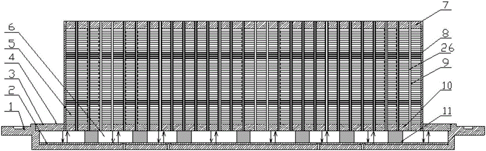
[0047] like Image 6 As shown, an auxiliary metal fiber layer is provided on the side wall of the support structure 11 in this embodiment, and the capillary channel of the metal fiber layer at the top and bottom of the evaporation chamber 6 is connected through the auxiliary metal fiber layer, that is, on the outside of the support structure 11 The capillary fiber ring 21 is assembled, and the capillary fiber ring 21 is formed by stamping or moulding. The specific manufacturing process of this embodiment is:

[0048] (1) According to the design requirements, the extrusion process is used to complete the forming of the multi-channel parallel heat pipe 9 of the aluminum flat belt type. The shape of the phase change channel 26 is rectangular, the size is 2mm*2mm, the wall thickness is 0.5mm, and the secondary structure is U The shape of the groove 15, the width and height dimensions are 0.2mm*0.2mm, and the circle diameter is 0.2mm, and the inner cavity of the phase change chann...

Embodiment 2

[0056] like Figure 7 , Figure 8a , Figure 8b and Figure 8c As shown, the end of the tube body of the multi-channel parallel heat pipe 9 described in this embodiment connected to the substrate is provided with a sawtooth structure. Fibrous layer contact. Capillary contact realizes rapid return of working fluid. Method 4 is mechanically contacting fibers with liquid absorption in flat belt heat pipe flanging and bending grooves. Cut out the zigzag structure 23 after the edge of the flat heat pipe is divided, and bend it so that the heat pipe micro-grooves directly contact the lower fiber layer 2 for reflow. Its specific manufacturing process is:

[0057] (1) According to the design requirements, the extrusion process is used to complete the forming of the multi-channel parallel heat pipe 9 of the aluminum flat belt. The shape of the channel is rectangular, the size is 2mm*2mm, the wall thickness is 0.5mm, and the secondary structure is an Ω-shaped groove. Groove 16 has...

Embodiment 3

[0065] like Figure 9 As shown, auxiliary grooves are provided on the side wall of the supporting structure 11 in this embodiment, and the method 4 of fast return flow of the working fluid by capillary contact is to assemble the auxiliary groove ring outside the supporting structure 11 . Machining or laser processing on the upper base plate 3 produces 6 micro-grooves in the evaporation cavity, and then simultaneously sinters the upper fiber layer 22 and the lower fiber layer 2 in the cavity surfaces of the upper base plate 3 and the lower base plate 1, and assembles auxiliary grooves outside the supporting structure 11 The ring 24 is reflowed. Its specific manufacturing process is:

[0066] (1) According to the design requirements, the extrusion process is used to complete the forming of the multi-channel parallel heat pipe 9 of the aluminum flat belt. The shape of the channel is rectangular, the size is 3mm*2mm, the wall thickness is 0.5mm, and the secondary structure is a r...


PUM


Abstract

The invention discloses a multi-channel parallel heat pipe radiator. The radiator comprises a substrate and a radiator box, wherein an evaporation cavity is formed inside the substrate, the radiator box comprises multi-channel parallel heat pipes and radiating fins arranged outside the multi-channel parallel heat pipes, the multi-channel parallel heat pipe comprises a hollow pipe body, a division plate is arranged inside the pipe body to divide the inner space of the pipe body into more than two phase change channels, the phase change channels are communicated with the evaporation cavity, the phase change channels and the evaporation cavity jointly form a sealed phase change heat exchange cavity, grooves are formed on the inner wall of the pipe body, and capillary channels are formed on the inner wall of the evaporation cavity. The multi-channel parallel heat pipe radiator furthest exerts the effect of a capillary structure, is compact in structure, small in floor area and high in heat transfer efficiency, solves the problems that the traditional water-cooled heat exchange system is huge and the like, and meets the high-power radiation requirement of a limited space.

Description

technical field [0001] The invention relates to a radiator, in particular to a multi-channel parallel heat pipe radiator. Background technique [0002] In the enhanced heat transfer technology at home and abroad, many high-efficiency phase-change heat transfer technologies have been developed by utilizing the characteristics of high heat transfer coefficient and uniform temperature of vapor condensation and liquid boiling evaporation. Water-cooling is mostly used in heat exchange systems of large-scale power electronic equipment. There are not many reports on the application of phase-change heat exchange systems. Water-cooling systems take up a lot of space and are heavy. Although the traditional plate radiator has a compact structure, the flow path is complex and the flow resistance on both sides of the medium is large. At the same time, the traditional plate radiator needs rubber ring sealing, which is not suitable for heat exchange with high-temperature steam. At the same...

Claims


Application Information

Patent Timeline
Patent Type & Authority Applications(China)
IPC IPC(8): F28D15/04
CPCF28D15/046
Inventor 迟兴国宗庆贺孙元邦高世驹谷立亚
Owner CRRC
Why Eureka
Try Eureka