Inflation and ignition integrated gas blaster igniter and cracker

A technology of detonating device and blaster, which is applied in the direction of blasting cylinder, compressed gas generation, weapon accessories, etc., which can solve the problems of high manufacturing cost, high drilling cost, complicated process, etc., and achieve the effect of high mixing uniformity

Inactive Publication Date: 2017-05-10
郭远军
View PDF1 Cites 1 Cited by
  • Summary
  • Abstract
  • Description
  • Claims
  • Application Information

AI Technical Summary

Problems solved by technology

[0006] The detonating device with the above structure has the following problems: 1. The thermal reactants to be filled in the detonating device need to be processed by mixing, mixing, coiling or bagging, and the filling process is time-consuming. 2. During the filling process of the detonating device, the oxidant and reductant are prone to uneven mixing, resulting in low heat release efficiency; 3. The thermal reaction material needs to be mixed and filled in advance, and the temperature is too high during transportation. It is highly likely to cause combustion or explosion, and has a greater potential safety hazard; 4. Due to the delay of the detonating material or other situations, it is easy to appear the situation of squibs, and it is impossible to judge the cause of the squibs, so it cannot be eliminated by rowing the squibs Potential safety hazard; 5. The existing gas blaster detonation method uses a solid activator to burn to generate high temperature, which directly conducts heat to liquid carbon dioxide, causing the liquid carbon dioxide to gasify and expand, and its heat absorption efficiency of liquid carbon dioxide is low
[0008] According to the structural description of the above-mentioned existing gas blaster, it can be seen that two holes need to be opened in the plugging head with the gas charging and lead wire structure, which are respectively the filling port for filling and discharging the easily vaporized liquid and the lead wire for leading out the lead wire The problem of adopting this kind of structure is: 1. The plugging head with inflatable and lead wire structure, in the drilling process, the process is more complicated, labor-consuming and time-consuming. Larger, the sealing process is more difficult, and the problem of air leakage is prone to occur. If the hole diameter is small, the drilling will be larger and the drilling cost will be higher; 2. The lead hole needs to be filled with sealant, which is cured after sealing, and It is easy to cause deflation under high pressure; 3. High manufacturing cost

Method used


Image

  • Inflation and ignition integrated gas blaster igniter and cracker
  • Inflation and ignition integrated gas blaster igniter and cracker
  • Inflation and ignition integrated gas blaster igniter and cracker

Examples


Embodiment 1

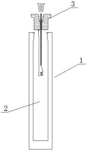
[0052] An inflatable and ignited integrated gas blaster detonating device, such as figure 1 As shown, it includes a housing 1, a filling chamber 2 and an inflatable ignition head 3. The housing 1 is a filling chamber 2, and one end of the housing 1 is connected to the inflatable ignition head 3. The compressive strength of the housing 1 is greater than 5.045Mpa;

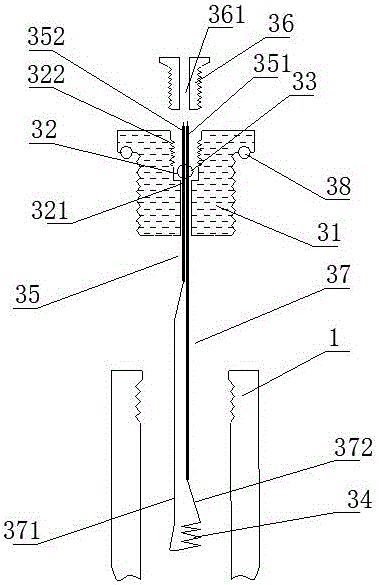
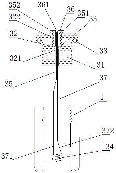
[0053] Such as figure 2 and image 3 As shown, the gas charging ignition head 3 includes a blocking base 31, an air filling hole 32, a sealing ball valve 33, a heating wire 34, a conductive joint 35 and a sealing locking screw 36, and the charging hole 32 penetrates the blocking base 31 from top to bottom, The lower part of the inflation hole 32 is provided with a sealing neck 321. The sealing ball valve 33 is installed above the sealing neck 321. The conductive joint 35 penetrates and is fixedly clamped on the sealing ball valve 33. The lower spherical surface of the sealing ball valve 33 is a matte surface withou...

Embodiment 2

[0059] The difference with embodiment 1 is: as Figure 4 As shown, the housing 1 includes a first segment body 11 and a second segment body 12, the first segment body 11 and the second segment body 12 are connected through a threaded structure, and are matched with a threaded sealing ring 13 for Sealing; the gas-filled ignition head 3 is respectively connected to one end of the first segment body 11 or the second segment body 11; this structure is convenient for charge.

Embodiment 3

[0061] The difference with embodiment 1 is: as Figure 5 As shown, the housing 1 is a composite layer tube containing fiber material, the housing 1 is made of composite layers, the housing 1 includes a matrix layer 101, a fiber layer 102 and a hardened layer 103, and the hardened layer 103 is located at The outer layer of the fiber layer 102, the matrix layer 101 is located in the inner layer of the fiber layer 102; the two ends of the housing 1 are respectively sealed and wrapped with a first metal joint 111 and a second metal joint 112, and the first metal joint 111 is threaded The sealed connection structure is connected to the gas-filled ignition head 3, and the second metal joint 112 is a closed head;

[0062] As a further description of the above embodiment, the base layer 101 is made of polyethylene (PE); the fiber layer 102 is made of glass fiber; the hardened layer 103 is made of epoxy resin.

[0063] As a further description of the above embodiment, the implementati...


PUM

PropertyMeasurementUnit
compressive strengthaaaaaaaaaa
thicknessaaaaaaaaaa
thicknessaaaaaaaaaa

Abstract

The invention discloses an inflation and ignition integrated gas blaster igniter and a cracker. The integrated gas blaster igniter comprises a shell, a filling cavity in the shell and an inflation and ignition head connected to one end of the shell, wherein the inflation and ignition head comprises a plugging base body, an inflation hole, a seal ball valve, a conductive contact and a seal lock screw; the inflation hole penetrates through the plugging base body from top to bottom, a seal necking hole is formed at the lower part of the inflation hole, the seal ball valve is installed above the seal necking hole, the conductive contact penetrates through and is fixedly clamped on the seal ball valve, the lower ball surface of the seal ball valve is a rough surface, an internal threaded hole is formed at the upper part of the inflation hole and is in threaded connection with the seal lock screw, a contact window through which the conductive contact penetrates is formed in the middle of the seal lock screw, and the conductive contact is connected with the heating wire via a lead. The integrated gas blaster igniter and the cracker have the advantages of simple powder charging process, good safety, high mixing uniformity, as well as low manufacturing cost and good sealing property of the inflation and ignition structure.

Description

technical field [0001] The invention belongs to the field of detonating devices, in particular to a detonating device for an integrated gas blaster with charging and ignition. Background technique [0002] Gas blasting technology is to use the vaporization and expansion of easily vaporized liquid or solid substances to generate high-pressure gas, which makes the surrounding medium expand to do work and cause fragmentation. It has the characteristics of no open flame, safety and high efficiency. [0003] Carbon dioxide gas blasters are typical blasting equipment in gas blasting technology, and are widely used in mining, geological exploration, cement, steel, electric power and other industries, subways and tunnels, municipal engineering, underwater engineering, and emergency rescue. [0004] Existing gas blasters mainly include a vaporization liquid storage pipe and a heating detonator installed in the vaporization liquid storage pipe; the heating detonation device ignites an...

Claims


Application Information

Patent Timeline
Patent Type & Authority Applications(China)
IPC IPC(8): F42B3/04F42B3/10F42B3/103F42B3/11F42B3/18C06D5/10C06B33/00C06B47/12C06B47/06C06B47/02C06B27/00
CPCF42B3/045C06B27/00C06B33/00C06B47/02C06B47/06C06B47/12C06D5/10F42B3/10F42B3/103F42B3/11F42B3/18
Inventor 郭远军
Owner 郭远军
Why Eureka
Try Eureka