
Pulse impedance particle counting device based on non-uniform electric field and particle counting method

A non-uniform electric field, particle counting technology, applied in measurement devices, individual particle analysis, particle and sedimentation analysis, etc., can solve problems such as complex processing steps, detection channel blockage, detection interruption, etc., to achieve high detection stability and improve reliability. Noise ratio, the effect of improving detection accuracy

Pending Publication Date: 2017-05-10
DALIAN MARITIME UNIVERSITY +1
View PDF12 Cites 11 Cited by
  • Summary
  • Abstract
  • Description
  • Claims
  • Application Information

AI Technical Summary

Problems solved by technology

However, it should be noted that in order to obtain a higher detection signal-to-noise ratio, the current counting chip often needs to make the detection channel size similar to the particle size, and the detection of corresponding nanoparticles also needs to process nanometer-sized detection channels. But this requires extremely complex processing steps and expensive processing equipment
[0012] In addition, since the size of the detection channel is relatively close to the particles, it is easy to cause particles to block the detection channel; at the same time, impurities in the solution will also cause partial or even complete blockage of the detection channel, resulting in errors in particle size detection results or detection interruptions, affecting The accuracy and stable operation of the system

Method used


Image

  • Pulse impedance particle counting device based on non-uniform electric field and particle counting method
  • Pulse impedance particle counting device based on non-uniform electric field and particle counting method

Examples


Embodiment Construction

[0037] In order to make the purpose, technical solutions and advantages of the present invention clearer, the technical solutions of the present invention will be clearly and completely described below in conjunction with the accompanying drawings in the embodiments of the present invention. Obviously, the described embodiments are part of the implementation of the present invention. example, not all examples. Based on the embodiments of the present invention, all other embodiments obtained by those of ordinary skill in the art without creative efforts shall fall within the protection scope of the present invention.

[0038] When the particles flow through the micropore with electric field, it will produce obvious disturbance to the electric field, and the voltage at both ends of the corresponding micropore will change to generate a voltage pulse signal. By detecting the number of voltage pulse signals, the number of sample particles can be detected.

[0039] Based on the abo...


PUM


Abstract

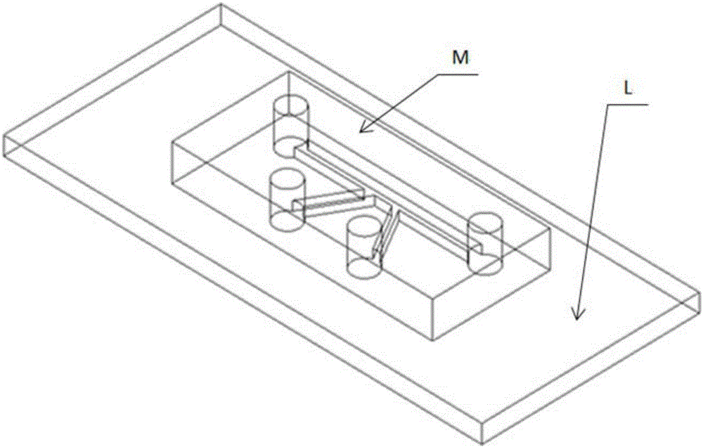
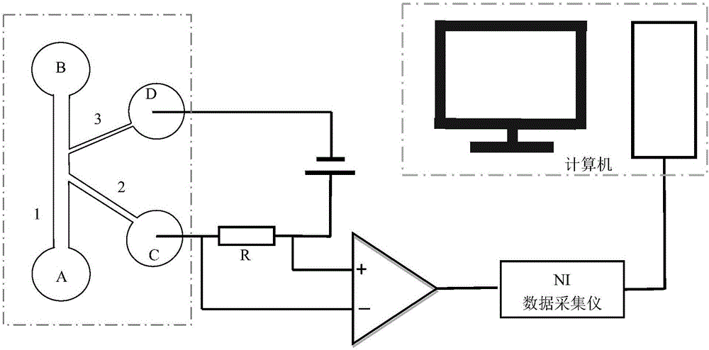
The invention discloses a pulse impedance particle counting device based on non-uniform electric field and a particle counting method; the pulse impedance particle counting device comprises a glass baseplate, a PDMS (polydimethylsiloxane) microfluidic chip, a signal amplifying element and a signal collection control system; the PDMS microfluidic chip is provided with a microchannel by means of indenting, and the microchannel includes: a main channel with two ends provided with an oil incoming liquid-storing hole and an oil outgoing liquid-storing hole respectively; a sample injection channel extending from the middle of the main channel to a direction leaving the main channel, wherein the tail end of the sample injection channel is provided with a sample injection channel liquid-storing hole; a detection channel extending from a position, a certain distance away from an intersection of the main channel and the sample injection channel, to a direction leaving the main channel, wherein a ratio of the width of the detection channel to the width of the main channel is fixed, and the tail end of the detection channel is provided with a detection channel liquid-storing hole. The pulse impedance particle counting device is simple in structure and high in detection precision, and can provide detection and counting with no need for particles to accessing a detection area.

Description

technical field [0001] The invention relates to the technical field of particle detection, in particular to a non-uniform electric field-based impedance pulse particle counting device and a counting method thereof. Background technique [0002] Accurately counting particles in samples is of great significance and demand in many fields; for example, in the fields of biomedical research, public health detection, and marine There is an urgent need for a portable particle fast counting device or method for the number of microorganisms, etc. [0003] At present, the commonly used particle counting methods include the following: [0004] 1) Photoblocking method (principle of optical interference): Photoblocking method is the most widely used particle counting method at present, also known as light obstacle method or light occlusion method, which uses the change of light intensity caused by the occlusion of light by particles to count particles. method of diameter detection. Thi...

Claims


Application Information

Patent Timeline
Patent Type & Authority Applications(China)
IPC IPC(8): G01N15/10
CPCG01N15/1031G01N15/1023G01N2015/1024
Inventor 宋永欣周侗王琪
Owner DALIAN MARITIME UNIVERSITY
Learn More