
Optical fiber collimator assembling and adjusting device

An optical fiber collimator and optical fiber technology, which is applied in the field of optical communication, can solve the problems of increasing production cost, optical fiber damage, and reducing installation and adjustment efficiency, and achieves the effects of improving consistency, high alignment accuracy, and simple structure

Pending Publication Date: 2017-05-10
SUZHOU INST OF BIOMEDICAL ENG & TECH CHINESE ACADEMY OF SCI
View PDF7 Cites 2 Cited by
  • Summary
  • Abstract
  • Description
  • Claims
  • Application Information

AI Technical Summary

Problems solved by technology

[0003] In the prior art, during the assembly process of fixing the optical fiber and the optical fiber collimator (with an optical lens assembly for collimating the light beam in the optical fiber) with ultraviolet photosensitive adhesive, it is often necessary for the operator to manually align the optical fiber and the optical fiber collimator, align The alignment accuracy of the injection component and the fiber collimator and the glue injection point aligned with the ultraviolet light source and the fiber collimator is not high; the ultraviolet light source is aligned with the fiber collimator glue injection place to irradiate for curing, and it takes a long time (5 minutes or so)
Moreover, in the process of assembling or curing, if the operator accidentally touches the optical fiber or fiber collimator being assembled or cured, the relative position between the optical fiber and the fiber collimator is often not the expected ideal position, As a result, the stability and accuracy of optical signal transmission are greatly reduced; especially in the case where multiple optical signals are required to be transmitted in parallel, the accuracy and consistency of the relative position between the optical fiber and the optical fiber collimator are directly related to the optical signal transmission. speed and bit error rate; moreover, the detection after assembly is often carried out after the optical fiber and fiber collimator have been cured by ultraviolet photosensitive adhesive, if the assembly effect is not good, often the optical fiber and fiber collimator will be It is scrapped, or it takes a lot of manpower and material resources to remove the UV photosensitive adhesive. Because the optical fiber itself is relatively fragile, the optical fiber will be damaged to a certain extent during the glue removal process, which greatly reduces the installation efficiency. Increased production cost

Method used


Image

  • Optical fiber collimator assembling and adjusting device
  • Optical fiber collimator assembling and adjusting device
  • Optical fiber collimator assembling and adjusting device

Examples


specific Embodiment approach

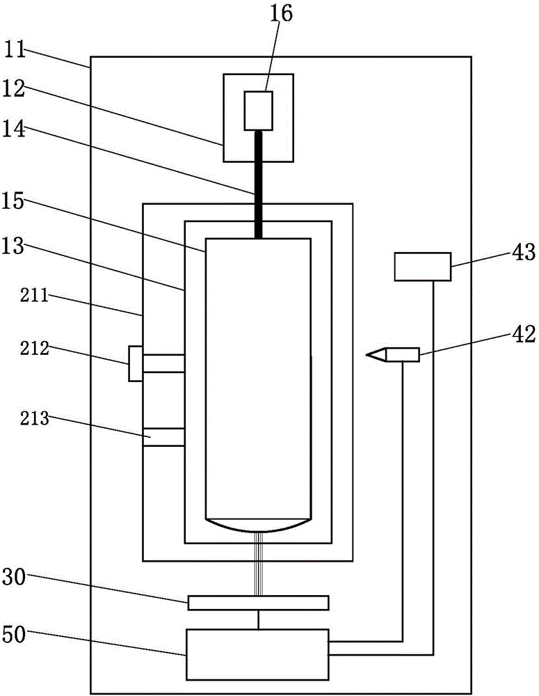
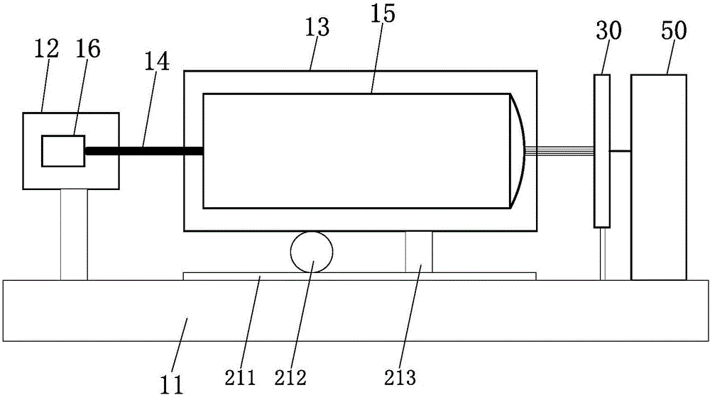
[0032] As another specific embodiment of the present invention, the optical fiber collimator installation and adjustment device also includes a controller 50, which is connected to the first displacement adjustment assembly 21, the spot imaging device 30, the second displacement adjustment assembly 22 and the third displacement adjustment assembly 21 respectively. The displacement adjustment assembly 23; the spot imaging device 30 sends the real-time spot information output by the fiber collimator 15 to the controller 50, and the controller 50 processes and analyzes the real-time spot information. image effect, the controller 50 sends drive information to drive the first displacement adjustment assembly 21 so that the second fixed assembly 13 moves relative to the base 11 to adjust the relative position between the fiber collimator 15 and the optical fiber 14; if the real-time spot information meets the control If the spot image effect pre-stored in the controller 50 is used, t...


PUM


Abstract

The invention discloses an optical fiber collimator assembling and adjusting device. The optical fiber collimator assembling and adjusting device comprises a fixing unit, the fixing unit comprises a pedestal, a first fixing assembly and a second fixing assembly which are arranged on the pedestal, an optical fiber which is horizontally arranged is fixed on the first fixing assembly, and an optical fiber collimator which is horizontally arranged is fixed on the second fixing assembly; the optical fiber collimator assembling and adjusting device also comprises a displacement adjusting device comprising a first displacement adjusting assembly arranged between the second fixing assembly and the pedestal, and the first displacement adjusting assembly drives the second fixing assembly to move relative to the pedestal; the optical fiber collimator assembling and adjusting device also comprises a light spot imaging unit which horizontally aligns to the light emitting terminal of the optical fiber collimator; the optical fiber is coupled with a laser light source; and the optical fiber can be movably inserted into the axle center of the optical fiber collimator. With respect to the optical fiber collimator assembling and adjusting device, under the imaging aid of the light spot imaging unit, and the first displacement adjusting assembly drives the second fixing assembly to move relative to the pedestal in order to adjust the relative plug-in position of the optical fiber collimator and the optical fiber, the optical fiber collimator assembling and adjusting device is simple in structure and high in aligning precision, and the imaging consistency is improved.

Description

technical field [0001] The invention relates to the technical field of optical communication, and more specifically, the invention relates to a device for installing and adjusting an optical fiber collimator. Background technique [0002] Optical fiber transmission has the advantages of wide frequency band, low loss, light weight, strong anti-interference ability, high fidelity, and reliable working performance. It is widely used in communication, medical, industry, national defense, aviation, aerospace, ships and other fields. In the high-throughput and high-speed signal transmission system between relatively rotating parts, it is often necessary to transmit multiple optical signals in an equal-length mode to eliminate the optical path difference and ensure the accuracy and speed of the transmitted signal. It is particularly important to ensure the consistency and accuracy of the relative positions of each optical fiber and fiber collimator. [0003] In the prior art, duri...

Claims


Application Information

Patent Timeline
IPC IPC(8): G02B7/00
CPCG02B7/005
Inventor 刘敏潘力付威威董月芳周哲陈奭
Owner SUZHOU INST OF BIOMEDICAL ENG & TECH CHINESE ACADEMY OF SCI
Learn More