Precision positioning device and method of dry plate for laser holographic direct printing

A technology of laser holography and precise positioning, which is applied in the field of holography, can solve problems such as inapplicability, and achieve the effect of simple structure, accurate and efficient precision positioning method

Active Publication Date: 2017-05-10
ACADEMY OF ARMORED FORCES ENG PLA
View PDF12 Cites 3 Cited by
  • Summary
  • Abstract
  • Description
  • Claims
  • Application Information

AI Technical Summary

Problems solved by technology

Patent CN104181131B proposed an infrared modulation photoluminescence two-dimensional imaging optical path automatic positioning and calibration device, patent CN2555526Y designed a real-time holographic interference precision reset fine-tuning holographic dry plate support, but the above method is not suitable for laser holographic direct printing system
At present, when performing laser holographic direct printing, most of them rely on manual experience or use a bi-telecentric lens with a large focal depth to overcome this defect, and there is no method to quickly and accurately avoid defocusing.

Method used


Image

  • Precision positioning device and method of dry plate for laser holographic direct printing
  • Precision positioning device and method of dry plate for laser holographic direct printing
  • Precision positioning device and method of dry plate for laser holographic direct printing

Examples


Embodiment Construction

[0019] In order to make the purpose, technical solution and advantages of the present invention more clear, the implementation of the "dry plate precision positioning device and method for laser holographic direct printing" of the present invention will be further described in detail below with reference to the accompanying drawings.

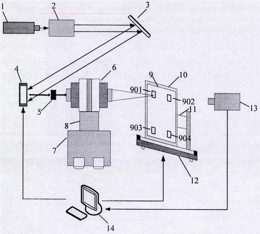
[0020] figure 1 The structure schematic diagram of the first embodiment of the dry plate precision positioning device and method for laser holographic direct printing provided by the present invention, including a light source (1), a beam expander collimating mirror (2), a plane mirror (3), a space Optical modulator (4), aperture stop (5), bi-telecentric lens (6), manual digital display translation stage (7), scissor lift stage (8), standard inspection dry plate (9), holographic dry plate A clamping part (10), a two-dimensional angle precision regulator (11), a displacement platform (12), a CCD camera (13), and a computer (14). By the laser eng...


PUM


Abstract

The invention belongs to the field of holography, and particularly relates to a precision positioning device and method of a dry plate for laser holographic direct printing. The precision positioning device of the dry plate comprises a light source, an expanded beam collimating lens, a flat reflector, a spatial light modulator, an aperture diaphragm, a double telecentric lens, a manual digital display translation stage, a scissor-type lifting platform, a standard test dry plate, a holographic dry plate clamping part, a two-dimensional angle precision regulator, a displacement platform, a CCD camera and a computer, wherein the standard test dry plate and the holographic dry plate clamping part are specially processed and manufactured; and the precision positioning method of the dry plate comprises the steps of observing a diffraction image of the spatial light modulator by using the CCD camera; cooperatively adjusting the two-dimensional angle precision regulator, the manual digital display translation stage and the scissor-type lifting platform according to certain order and method; and finally ensuring that the distance between the dry plate and the double telecentric lens is within a clear imaging range of the lens. The defocus phenomenon caused during laser holographic direct printing is avoided and the printing and reappearing effects of a hologram are improved.

Description

technical field [0001] The invention belongs to the field of holography, and in particular relates to a dry plate precision positioning device and method for direct printing of laser holography. Background technique [0002] After the holographic interference fringes are calculated by the computer, the technology of printing the interference fringes block by block on the holographic recording medium through the bi-telecentric lens microsystem is called laser holographic direct printing technology. Due to the limited clear imaging distance of the bi-telecentric lens, that is, the depth of field of the image square, when the distance between the dry plate and the bi-telecentric lens is not within this range, the calculated holographic fringes printed on the holographic recording medium will produce defocusing phenomenon, which means It will lead to a decrease in the reproduction quality of the hologram, and even the original cannot be reproduced. Since the holographic dry pla...

Claims


Application Information

Patent Timeline
IPC IPC(8): G03H1/04G03H1/12
CPCG03H1/0476G03H1/12
Inventor 闫兴鹏苏健蒋晓瑜黄应清陈祎贝任秀英宋振中严志强徐丙立
Owner ACADEMY OF ARMORED FORCES ENG PLA
Why Eureka
Try Eureka