Linear voltage-stabilizing device

A technology of linear voltage regulator and linear voltage regulator, which is applied in the direction of adjusting electrical variables, control/regulation systems, instruments, etc., can solve the problems of increasing cost, increasing chip area and power consumption, occupying a large area, etc., and achieving reduction Effects of performance degradation, reduction in chip area and power consumption

Active Publication Date: 2017-05-10
安徽矽磊电子科技有限公司
View PDF4 Cites 1 Cited by
  • Summary
  • Abstract
  • Description
  • Claims
  • Application Information

AI Technical Summary

Problems solved by technology

In the design of the first reference reference circuit, in order to withstand a higher power supply voltage, it is often necessary to adopt the method of stacking transistors to reduce the reliability requirements of high voltage on the transistor; in addition, because the reference reference circuit often adopts a bandgap reference structure , so it generally takes up a larger area; and in the design of the second reference reference circuit, although the withstand voltage requirement is not high, in order to achieve better performance, the reference reference circuit generally uses a diode with a larger area to achieve high Therefore, designing two reference circuits with different requirements will not only greatly increase the chip area and power consumption, but also increase the cost, and the design difficulty will also increase.

Method used


Image

  • Linear voltage-stabilizing device
  • Linear voltage-stabilizing device
  • Linear voltage-stabilizing device

Examples


Embodiment 1

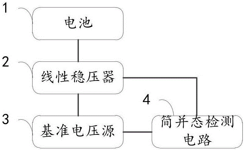
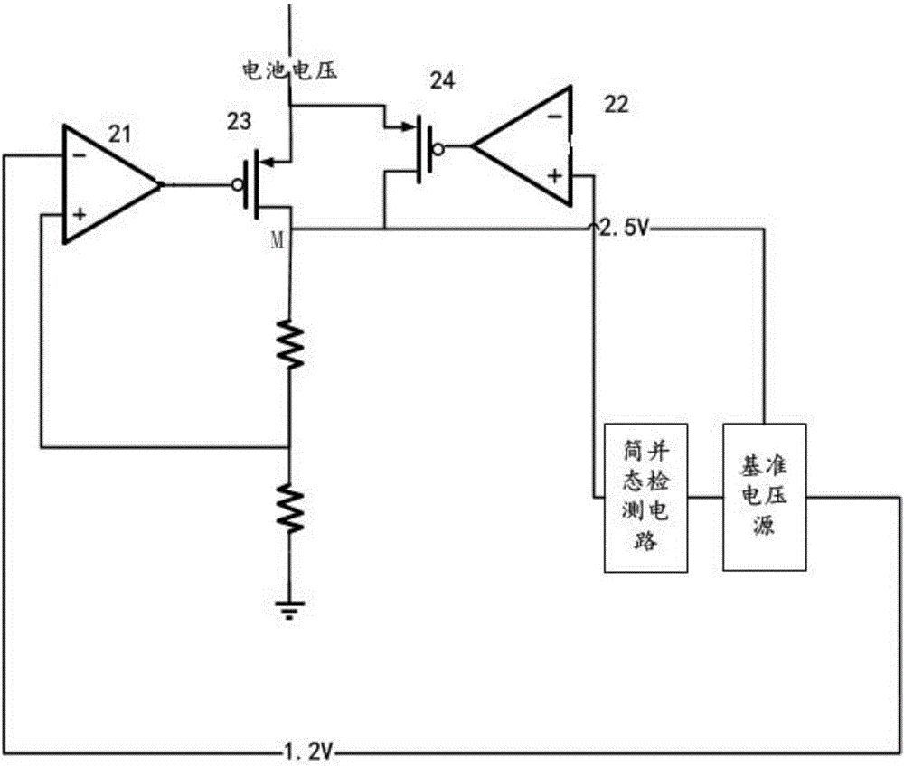
[0047] Example 1, such as figure 2 As shown, the degenerate state detection circuit 4 is used to detect the degenerate state in the circuit of the reference voltage source 3, if the degenerate state is not detected, the circuit will close the PMOS transistor 24 through the amplifier 22, and the circuit works normally; when the degenerate state When the detection circuit 4 detects that the output of the reference voltage source 3 circuit is low, the output polarity of the amplifier 22 is reversed, and the degenerate state detection circuit 4 turns on the PMOS transistor 24. At this time, the battery 1 is connected to the input terminal M of the reference voltage source 3. After charging, the voltage of the reference voltage source 3 gradually increases, and the reference voltage source 3 enters a normal working state. At the same time, the degenerate state detection circuit 4 is turned off and the PMOS tube 24 is controlled to be closed, and the circuit enters a normal working ...

Embodiment 2

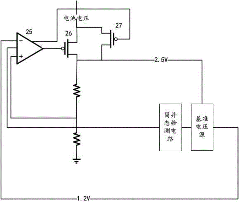
[0048] Example 2, such as image 3 As shown, the two amplifiers 21 and 22 in Embodiment 1 are combined into one amplifier 25 . When the reference voltage source 3 is in a normal state, the amplifier 25 is used to amplify the difference between the feedback voltage point and the output reference voltage of the reference voltage source 3, and control the opening and closing of the PMOS tube 26 according to the difference; and in the reference voltage source When 3 is the degenerate state, the amplifier 25 is used to eliminate the degenerate state, amplify the degenerate state detection signal and control the PMOS transistor 27 to charge the output node of the linear voltage regulator 2 until the degenerate state is completely eliminated.


PUM


Abstract

The invention relates to a linear voltage-stabilizing device. The linear voltage-stabilizing device comprises a battery, a linear voltage regulator and reference voltage sources, all of which are connected in order. The device further comprises a degenerate state detection circuit connected with the linear voltage regulator and the reference voltage sources. The linear voltage regulator is used for providing power sources to the reference voltage sources. The reference voltage sources are used for providing reference voltage sources required by the linear voltage regulator. The degenerate state detection circuit is used for detecting working states of the reference voltage sources and controlling the working states of the linear voltage regulator. The working states of the reference voltage sources comprise a degenerate state and a normal state. The linear voltage-stabilizing device has following beneficial effects: the technical scheme helps decrease the area and power consumption of a chip; process floating and deviation caused by the distance, the direction and other non-ideal factors for the two reference voltage sources are effectively reduced, thereby avoiding performance reduction of deviation-induced other circuits.

Description

technical field [0001] The invention relates to the technical field of linear voltage stabilizers, in particular to a linear voltage stabilizing device. Background technique [0002] Traditional circuits or modules connected to the battery voltage usually have two reference circuits, one of which is directly connected to the battery output voltage, and its main purpose is to provide a reference voltage for a linear regulated source. In addition, the reference circuit needs to be able to withstand a higher power supply voltage and a larger voltage variation range, so the accuracy of the output voltage is generally low. The power supply of another reference circuit uses the output voltage of a linear regulated source. Since the output voltage of the linear regulated source is relatively stable, the reference circuit has relatively loose requirements on the power supply voltage, but it often needs to provide higher output voltage accuracy. . In the design of the first referen...

Claims


Application Information

Patent Timeline
Patent Type & Authority Applications(China)
IPC IPC(8): G05F1/56
CPCG05F1/561
Inventor 王晗
Owner 安徽矽磊电子科技有限公司
Why Eureka
Try Eureka