
Design method of basic flow field of inward turning inlet with controllable flow field parameters of outlet section

A technology of internally turning inlet and basic flow field, which is applied in design optimization/simulation, sustainable transportation, special data processing applications, etc., can solve the compression law of restricted flow field, and take into account the starting and anti-backpressure of the inlet Capability is difficult, it is difficult to control the viscosity loss of the intake port, etc., to achieve the effect of weakening the intensity of mutual interference, expanding a given range, and improving aerodynamic performance

Active Publication Date: 2020-03-17
SOUTHWEAT UNIV OF SCI & TECH +1
View PDF4 Cites 0 Cited by
  • Summary
  • Abstract
  • Description
  • Claims
  • Application Information

AI Technical Summary

Problems solved by technology

Secondly, on the premise of not considering the existence, although the method of completely determining the basic flow field according to the outlet parameters is relatively simple, this method also limits the compression law of the flow field at the same time. bring some difficulties
In addition, the compression law of the flow field also has a great influence on the development of the boundary layer, so it is difficult to control the viscous loss of the inlet by using this method, and it is difficult to control the mutual interference between the reflected shock wave and the boundary layer
It can be seen that how to adjust the compression law of the flow field according to the outlet parameter distribution is another major obstacle that limits the application of this method.
[0006] Based on the above two reasons, the method of designing the basic flow field according to the distribution of outlet parameters is currently limited to the binary inlet, and the application in the design of the inlet of the internal rotation meter needs to be further studied

Method used

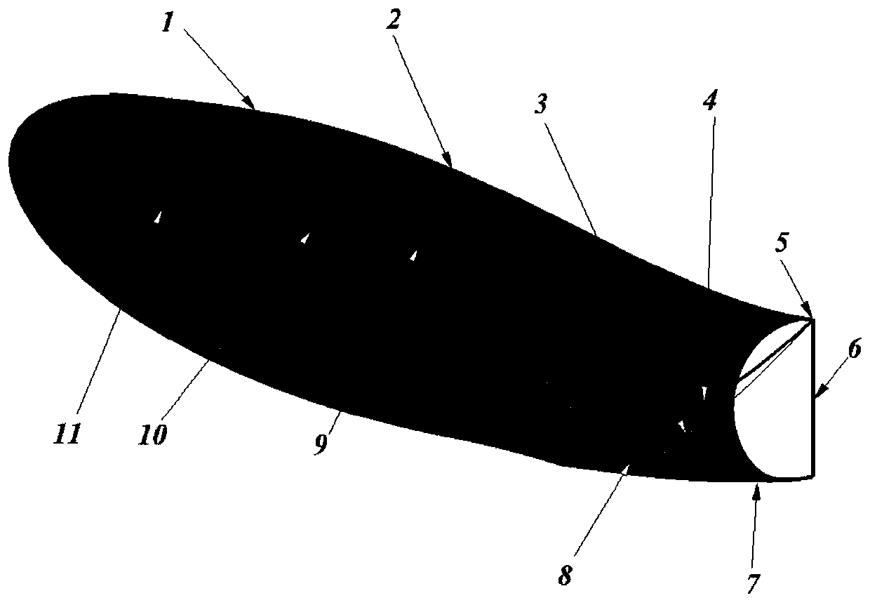

Image

  • Design method of basic flow field of inward turning inlet with controllable flow field parameters of outlet section
  • Design method of basic flow field of inward turning inlet with controllable flow field parameters of outlet section
  • Design method of basic flow field of inward turning inlet with controllable flow field parameters of outlet section

Examples


Embodiment 1

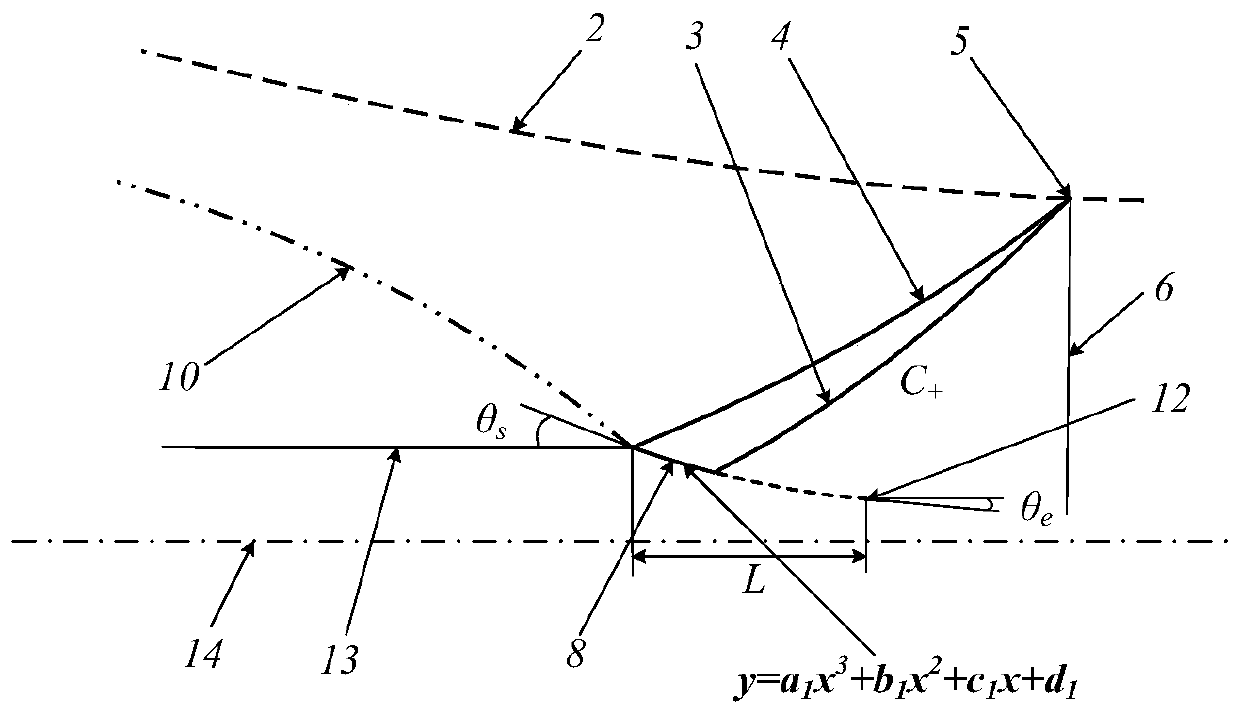
[0038] 1. If figure 2 , the design method of designing the boundary 8 that can generate the reflected shock wave 4 according to the flow field parameters at the vertex 5 of the reflected shock wave is to adjust the boundary 8 of the reflected shock wave 4 that can generate the basic flow field to control the basic flow field The shape of the reflected shock wave 4 makes the flow field parameters at the vertex 5 of the reflected shock wave consistent with the flow field parameters at the upper boundary of the outlet section 6 of the basic flow field, specifically including the following steps:

[0039] ① if figure 2 , using a cubic curve to describe the boundary 8 that generates the reflected shock wave, the curve is controlled by the starting point of the reflected shock wave 4 of the basic flow field and the position of the artificially given control point 12 and the direction angle of the airflow, and the control equation of the curve is y=a 1 x 3 +b 1 x 2 +c 1 ·x+d ...

Embodiment 2

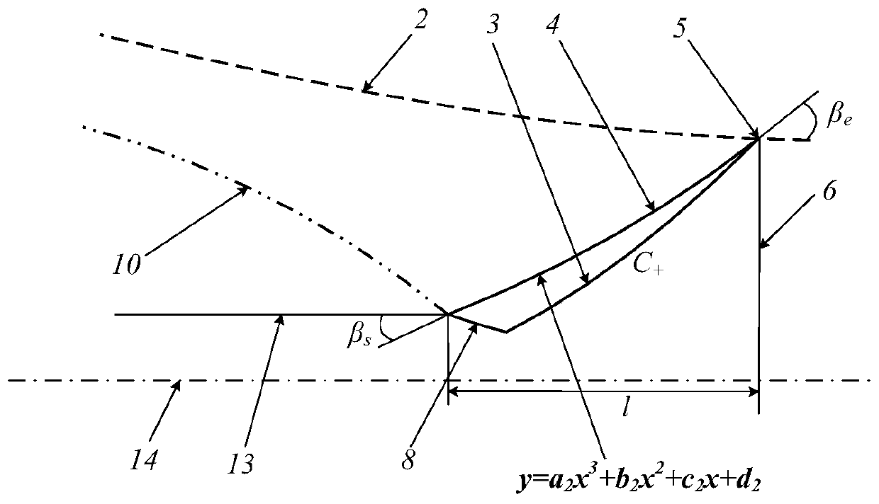
[0050] 1. If image 3 , the design method of designing the boundary 8 that can generate the reflected shock wave according to the flow field parameters at the vertex 5 of the reflected shock wave is to directly give The shape of the reflected shock wave 4 of the basic flow field, while ensuring that the flow field parameters at the vertex 5 of the reflected shock wave are consistent with the flow field parameters at the upper boundary of the outlet section 6 of the basic flow field, and then apply the given shock wave to inversely calculate The inverse characteristic line method of the surface determines the object surface that can generate the shock wave, including the following steps:

[0051]① On the upper boundary of the basic flow field, a point with a lateral distance l from the starting point of the reflected shock wave is taken as the apex 5 of the reflected shock wave, and the flow field parameters at this point are the wavefront flow field parameters. Parameter dist...


PUM


Abstract

The invention provides a design method for an internal rotation air inlet basic flow field with controllable outlet section flow field parameters. The shape of the lower boundary of the basic flow field is designed according to one kind of flow field parameter distribution of an outlet section. The method comprises the following steps: firstly, designing an aero-dynamic profile capable of generating reflected shock waves according to wave-back flow field parameters at the vertex of the reflected shock waves; and then, designing an aero-dynamic profile capable of adjusting wave-back dependence domain outlet downstream flow field parameters of the reflected shock waves to be consistent with the outlet section flow field parameters according to one type of flow field parameter distribution of the outlet section. Through adoption of the design method, only one parameter at the outlet section needs to be restrained, and the flow field parameter distribution at the outlet section is hardly restrained, so that the given range of given flow field parameters is enlarged. When the flow field parameter at the vertex of the reflected shock waves is controlled, the reflection of the reflected shock waves in an air inlet isolator can be effectively controlled, and meanwhile the strength of mutual interference between the reflected shock waves and a boundary layer is weakened, so that the aerodynamic performance of the air inlet is improved.

Description

technical field [0001] The invention relates to the design field of an inwardly rotating inlet whose Mach number is greater than 3, in particular to a basic flow field design method of an inwardly rotating inlet with controllable outlet section flow field parameters. Background technique [0002] In the past ten years, the internal rotation inlet has been widely used in the design of high Mach number (3<M<5) and hypersonic (M>5) air-breathing propulsion systems. In the basic flow field of the traditional revolving inlet, the reflected shock wave is generated by the lower boundary of the horizontal basic flow field. In this case, the compression process of the inlet to the incoming flow mainly includes inlet shock wave, isentropic compression, There are four parts of reflected shock wave and isolation section. Due to design reasons, the upper surface of the basic flow field of the traditional inward-turning inlet can not absorb the reflected shock wave well, which m...

Claims


Application Information

Patent Timeline
IPC IPC(8): G06F30/17G06F30/28
CPCG06F30/15G06F30/20Y02T90/00
Inventor 乔文友余安远吴颖川王宇辉黎崎
Owner SOUTHWEAT UNIV OF SCI & TECH
Learn More