E-jet printing method for solar photovoltaic cell electrode

A technology of photovoltaic cells and solar energy, applied in photovoltaic power generation, printing, circuits, etc., can solve the problem of limiting the open circuit voltage of photovoltaic cells, short-circuit current plane utilization, photoelectric conversion efficiency, difficulty in controlling the line width accuracy of secondary printed electrodes, increasing photovoltaic Solve problems such as battery manufacturing costs, achieve the effect of improving photoelectric conversion efficiency, improving plane utilization, and improving electrical performance

Active Publication Date: 2017-05-10
DALIAN UNIV OF TECH
View PDF5 Cites 23 Cited by
  • Summary
  • Abstract
  • Description
  • Claims
  • Application Information

AI Technical Summary

Problems solved by technology

Limited by the structure of the mesh plate and the properties of the slurry, it is difficult to further reduce the width of the electrode structure, so it is difficult to reduce the area of ​​the electrode on the battery plate, resulting in difficulty in reducing the shadow loss
Although the height of the electrode structure can be increased by secondary printing, there are problems such as difficult control of electrode line width accuracy and complex process in secondary printing, which limits the performance of photovoltaic cells such as open circuit voltage, short circuit current, plane utilization rate, and photoelectric conversion efficiency. Further improve
In addition, since screen printing is a contact manufacturing method, it directly applies pressure to the fragile semiconductor wafer, which is likely to cause damage such as cracks and breakage of the wafer.
Moreover, the utilization rate of the electrode paste for screen printing is limited, and the screen needs to be replaced frequently, which increases the manufacturing cost of photovoltaic cells

Method used


Image

  • E-jet printing method for solar photovoltaic cell electrode
  • E-jet printing method for solar photovoltaic cell electrode

Examples


Embodiment Construction

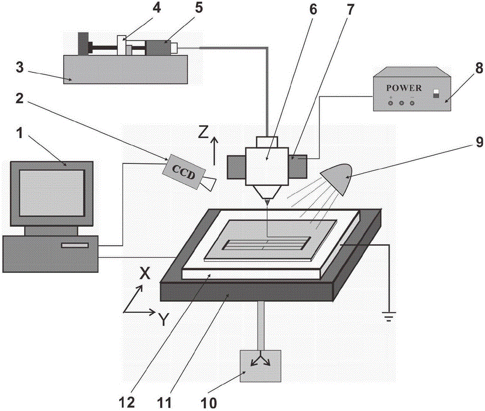
[0024] The specific implementation manners of the present invention will be described in detail below in conjunction with the technical solutions and accompanying drawings. The jet printing device of the embodiment is mainly composed of four parts: a fluid jet printing module, a motion module, a micro vision module and a control module.

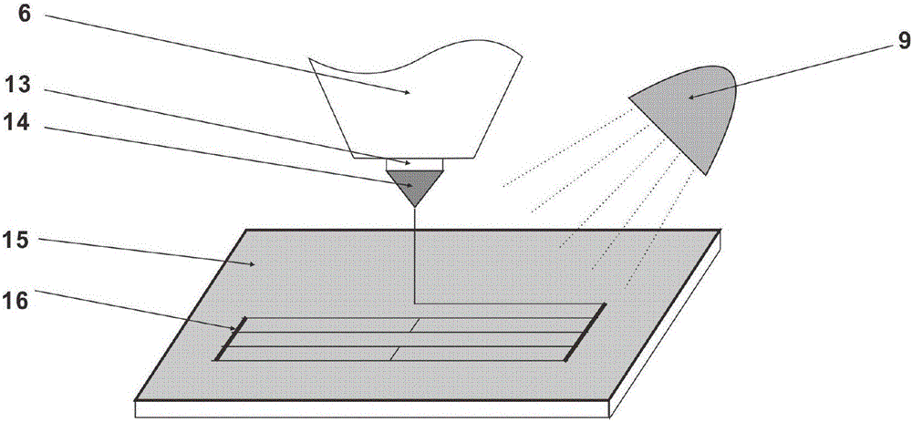
[0025] The syringe 4 is fixed on the top of the syringe pump 3, and the conductive ink 5 is housed in the syringe 4, and the syringe 4 is connected with the upper inlet of the nozzle 6 through a conduit. The nozzle 6 is made of conductive material, and the head is processed with a nozzle hole 13 with an inner diameter of 100 microns, and is positioned and clamped by the nozzle clamp 7 . The rear end of the nozzle clamp 7 is insulated and fixed on the Z displacement axis that can move longitudinally; the front end is conductive and clamps the nozzle 6 . The output end of the voltage controller 8 is connected to the right end of the shower hea...


PUM


Abstract

The invention belongs to the technical field of advanced manufacturing and provides an e-jet printing method for a solar photovoltaic cell electrode. Firstly, fluid pressure is applied to conductive ink, and the conductive ink flows out of a nozzle hole at a certain flow speed; then, a certain electric field is applied to the conductive ink, fine jet far smaller than the inner diameter of the hole is thus formed; the jet is then heated, and the partial solvent of the conductive ink is evaporated; and finally, jet printing of an electrode structure on a heated photovoltaic cell semiconductor sheet is carried out, the conductive ink is quickly cured, and a photovoltaic cell electrode structure is formed. The comprehensive effects on the conductive ink by the electric field-thermal field are used and control on the moving track of the solar photovoltaic cell semiconductor sheet by a moving platform is matched, and thus, the solar photovoltaic cell electrode is made. The electrode structure jet printing technology provided by the invention has the advantages of simple process, easy control, high precision and strong material adaptability, and making of a large-height-width ratio electrode structure in high temperature can be realized.

Description

technical field [0001] The invention belongs to the field of advanced manufacturing technology, and relates to a method for electro-spray printing solar photovoltaic battery electrodes. Background technique [0002] Solar photovoltaic cells (hereinafter referred to as photovoltaic cells) can directly convert solar energy into electrical energy, and its principle is the photovoltaic effect. Silicon solar cells are currently the most mature and dominate battery applications. [0003] Silicon solar cells are mainly composed of upper electrodes, lower electrodes, n-type semiconductors, p-type semiconductors, and p-n junctions. The upper and lower electrodes are directly connected to the load and output voltage to the load, which is the key to affecting the series resistance and photoelectric conversion efficiency of photovoltaic cells. Photovoltaic cells generally use silver as an electrode material, and silver electrodes are also an important part that affects the cost of phot...

Claims


Application Information

Patent Timeline
Patent Type & Authority Applications(China)
IPC IPC(8): H01L31/0224H01L31/18B41J2/01
CPCB41J2/01H01L31/022425H01L31/1876Y02E10/50
Inventor 王大志孟庆博王强李凯梁军生任同群冯立韦运龙
Owner DALIAN UNIV OF TECH
Why Eureka
Try Eureka