Three-phase inverter topology structure with adjustable DC bus voltage and method of adopting structure to realize dynamic DC bus voltage adjustment

A DC bus voltage, three-phase inverter technology, applied in the direction of electronically commutated motor control, motor generator control, electromechanical brake control, etc., can solve the problems of increased motor loss, torque fluctuation, etc.

Active Publication Date: 2017-05-10
HARBIN INST OF TECH
View PDF6 Cites 21 Cited by
  • Summary
  • Abstract
  • Description
  • Claims
  • Application Information

AI Technical Summary

Problems solved by technology

[0010] The purpose of the present invention is to solve the large torque fluctuations in the controlled high-speed motor caused by the existing inverter topology, and the square wave vo...

Method used


Image

  • Three-phase inverter topology structure with adjustable DC bus voltage and method of adopting structure to realize dynamic DC bus voltage adjustment
  • Three-phase inverter topology structure with adjustable DC bus voltage and method of adopting structure to realize dynamic DC bus voltage adjustment
  • Three-phase inverter topology structure with adjustable DC bus voltage and method of adopting structure to realize dynamic DC bus voltage adjustment

Examples


specific Embodiment approach 1

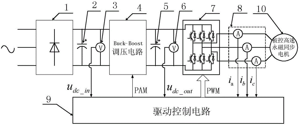
[0050] Specific implementation mode one: see figure 2 Describe this embodiment, the three-phase inverter topology structure with adjustable DC bus voltage described in this embodiment, which includes a three-phase rectifier bridge 1, a DC bus support capacitor 2, a DC bus input voltage detection module 3, and a Buck-Boost Voltage regulation circuit 4, DC bus output voltage stabilizing capacitor 5, DC bus output voltage detection module 6, three-phase half-bridge inverter circuit 7, three-phase current detection module 8 and drive control circuit 9;

[0051] The three-phase rectifier bridge 1 converts the received three-phase AC or single-phase AC into a DC voltage, and the DC voltage is stabilized by the DC bus support capacitor 2 and then input to the Buck-Boost voltage regulation circuit 4, and the Buck-Boost voltage regulation circuit 4 according to Drive the PAM control signal output by the control circuit 9 to adjust the voltage amplitude output by the Buck-Boost voltage...

specific Embodiment approach 2

[0063] Specific implementation mode two: see figure 2 To illustrate this embodiment, the DC bus voltage dynamic adjustment method realized by the three-phase inverter topology structure with adjustable DC bus voltage described in the first specific embodiment, the specific process of the adjustment method is as follows:

[0064] First, the drive control circuit 9 detects in real time the DC voltage output by the three-phase rectifier bridge 1, the voltage output by the Buck-Boost voltage regulator circuit 4, and the three-phase current i output by the three-phase half-bridge inverter circuit 7 a , i b , i c ;

[0065] Among them, the output voltage of the three-phase rectifier bridge 1 is the input voltage u of the DC bus dc_in ,

[0066] The voltage output by the Buck-Boost voltage regulating circuit 4 is the output voltage u of the DC bus dc_out ;

[0067] Secondly, the drive control circuit 9 according to the external given instruction speed n cmd , to receive the i...

specific Embodiment approach 3

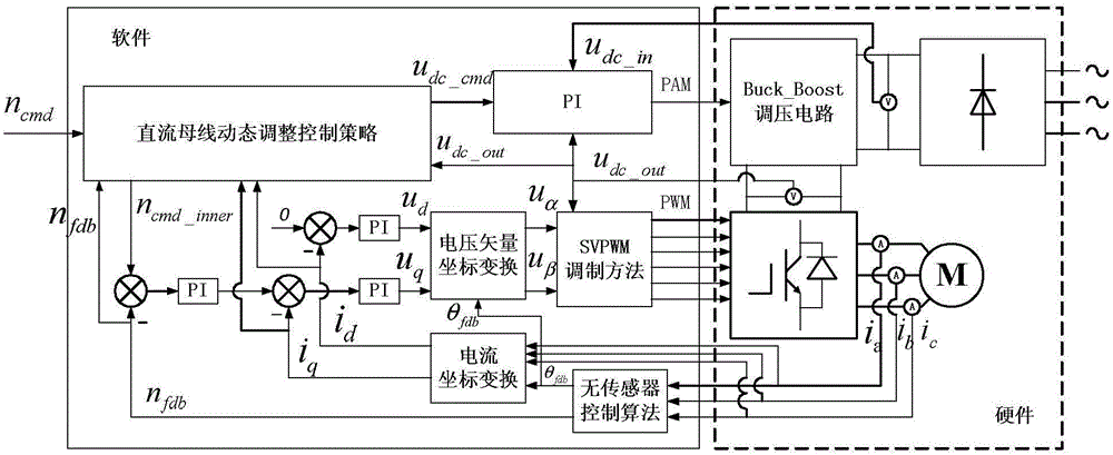
[0068] Specific implementation mode three: see image 3 This embodiment is described. The difference between this embodiment and the method for dynamically adjusting the DC bus voltage realized by using the three-phase inverter topology structure with adjustable DC bus voltage described in the second embodiment is that the drive control circuit 9 is based on External given command speed n cmd , to receive the input voltage u of the DC bus dc_in , the output voltage u of the DC bus dc_out and three-phase current i a , i b , i c process to make it generate a PAM control signal and a PWM control signal, and perform closed-loop control on the Buck-Boost voltage regulating circuit 4 through the PAM control signal, thereby controlling the output voltage u of the DC bus dc_out Perform dynamic adjustment, control the three-phase half-bridge inverter circuit 7 through the PWM control signal, thereby driving the controlled high-speed permanent magnet synchronous motor 10, and make ...


PUM


Abstract

The invention discloses a three-phase inverter topology structure with adjustable DC bus voltage and a method of adopting the structure to realize dynamic DC bus voltage adjustment, which belong to the field of high-speed motor spindle driving control, and solve the problem that the existing inverter topology structure results in huge torque ripple in a controlled high-speed motor, applied square wave voltage during the control process generates current harmonics rich in a harmonic spectrum, and thus, loss in the motor is increased abruptly. The topology structure comprises a three-phase rectifier bridge, a DC bus supporting capacitor, a DC bus input voltage detection module, a Buck-Boost voltage adjusting circuit, a DC bus output voltage stabilizing capacitor, a DC bus output voltage detection module, a three-phase half-bridge inverter circuit, a three-phase current detection module and a driving control circuit. The dynamic bus voltage adjustment method is realized by adopting a DC bus voltage online dynamic adjustment strategy and a sensorless control strategy. The structure and the method are mainly used to dynamically adjust the DC bus voltage according to a motor operation state.

Description

technical field [0001] The invention belongs to the field of high-speed motor spindle drive control. Background technique [0002] High-speed motors are high-tech products derived from the development of power electronics, material science, and microelectronics. They have important application values ​​in many industrial fields. Compared with conventional motors, the design and application of high-speed motors are mechanically affected by materials. Performance constraints: Due to the limitation of material stiffness and Young's modulus, the surface linear velocity and rotational angular velocity can make full use of the physical properties of materials compared with conventional motors during high-speed operation, so it has the advantages of other motors compared with conventional motors. Comparable advantages: [0003] (1) High-speed motors have small geometric dimensions and high power density, effectively saving physical materials and working space; [0004] (2) The mo...

Claims


Application Information

Patent Timeline
IPC IPC(8): H02P6/10H02P21/05
CPCH02P6/10H02P21/05
Inventor 李立毅刘家曦杜鹏程曹继伟于吉坤裴乐
Owner HARBIN INST OF TECH
Why Eureka
Try Eureka