Graphenic carbon particle co-dispersions and methods of making same
A technology of olefinic carbon particles and graphene carbon, which is applied in the field of co-dispersion, can solve the problem that graphene carbon particles are difficult to disperse
- Summary
- Abstract
- Description
- Claims
- Application Information
AI Technical Summary
Problems solved by technology
Method used
Image
Examples
Embodiment 1
[0078] The compositions summarized in Table 1 were dispersed by adding 70 g of the following compositions to an 8 oz glass jar with 220 g of SEPR Ermil 1.0-1.25 mm grinding media. All compositions were formulated to contain 60.95 g of N-methyl-2-pyrrolidone, 7.0 g of total graphene carbon particles, and 2.05 g of a solvent-borne block copolymer dispersant (comprising 43% by weight n-butyl acetate and 57% by weight % block copolymers disclosed in US 2008 / 0188610). The samples in the jar were shaken for 4 hours using a Lau disperser (model DAS 200, Lau, GmbH). After shaking, the dispersion was diluted with additional N-methyl-2-pyrrolidone and the grinding media was filtered off. The P / B (pigment to binder ratio) in each composition was 6.
[0079] Table 1
[0080] Dispersions
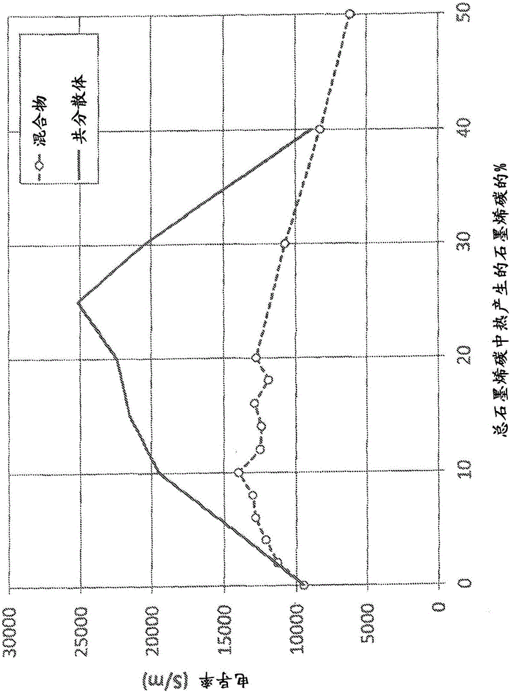
[0081] Sample: A B C D E F G H I J %M-25 0 100 100 90 85 80 75 70 60 50 %TGC 100 0 0 10 15 20 25 30 40 50 %TS 6.0 10.7 8.6 8.7 8.3 8.2 8.2...
Embodiment 2
[0084] Sample A from Table 1 containing only TGC graphene carbon particles was mixed with Sample B from Table 1 containing only M-25 graphene carbon particles at different ratios listed in Table 2 below. Each mixture was prepared by adding the appropriate amount of each sample together to a glass jar and stirring vigorously with a paddle until thoroughly mixed. The P / B for each of the resulting compositions was 6.
[0085] Table 2
[0086] mixture
[0087] Sample: 1 2 3 4 5 6 7 8 9 10 11 12 13 %M-25 98 96 94 92 90 88 86 84 82 80 70 60 50 %TGC 2 4 6 8 10 12 14 16 18 20 30 40 50
Embodiment 3
[0089] Specimens C to J from Table 1 and Specimens 1 to 13 from Table 2 were taken as 1-2 mm wide lines using a dispensing nozzle (PICO valve, MV-100, Nordson, EFD) and a tabletop robot (2504N, Janome). The serpentine circuit pattern was applied to 2 x 3 inch glass slides (Fisherbrand, Plain, Precleaned) and then dried in an oven at 212°F for 30 minutes. Conductivity is determined by first measuring the resistance of the serpentine circuit versus the length of the circuit wire. Then, the cross-sectional area of the serpentine line was measured using a pin profiler (Dektak). Using measurements of the cross-sectional area (A) and electrical resistance (R) for a given length (L) of the circuit, resistivity (ρ) is calculated using the equation ρ=RA / L. Conductivity (σ) was then calculated by taking the reciprocal of resistivity σ=1 / ρ. The conductivity results are shown in Table 3, expressed in units of Siemens / meter.
[0090] table 3
[0091] Conductivity
[0092]
[0093...
PUM
| Property | Measurement | Unit |
|---|---|---|
| electrical conductivity | aaaaa | aaaaa |
| electrical conductivity | aaaaa | aaaaa |
| electrical conductivity | aaaaa | aaaaa |
Abstract
Description
Claims
Application Information
 - R&D
- Intellectual Property
- Life Sciences
- Materials
- Tech Scout
- Unparalleled Data Quality
- Higher Quality Content
- 60% Fewer Hallucinations
Browse by: Latest US Patents, China's latest patents, Technical Efficacy Thesaurus, Application Domain, Technology Topic, Popular Technical Reports.
© 2025 PatSnap. All rights reserved.Legal|Privacy policy|Modern Slavery Act Transparency Statement|Sitemap|About US| Contact US: help@patsnap.com


