Constant velocity universal joint outer joint member and manufacturing method for same

一种万向联轴、制造方法的技术,应用在联轴器、弹性联轴器、刚性轴联轴器等方向,能够解决难杯状部与轴部一体成形等问题,达到削减不良率、削减制造成本、高焊接品质的效果

Active Publication Date: 2017-05-10
NTN CORP
View PDF7 Cites 4 Cited by
  • Summary
  • Abstract
  • Description
  • Claims
  • Application Information

AI Technical Summary

Problems solved by technology

In the long-rod outer coupling member, since the shaft is long, it is difficult to integrally form the cup and the shaft with high precision.

Method used


Image

  • Constant velocity universal joint outer joint member and manufacturing method for same
  • Constant velocity universal joint outer joint member and manufacturing method for same
  • Constant velocity universal joint outer joint member and manufacturing method for same

Examples


Embodiment Construction

[0088] Embodiments of the present invention will be described below based on the drawings.

[0089] First, refer to figure 1 and Figure 2a~2c The first example of the outer coupling member is described, and then, refer to Figure 3-16 A first example of the manufacturing method of the outer joint member will be described.

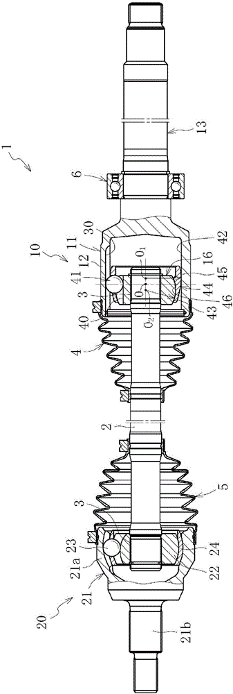
[0090] figure 1 Shows the overall structure of the drive shaft 1. The drive shaft 1 has a sliding constant velocity universal joint 10 , a fixed constant velocity universal joint 20 , and an intermediate shaft 2 connecting both the joints 10 , 20 as main components. The sliding type constant velocity universal joint 10 is arranged on the differential side (the right side in the figure: also called the inner disc side), and the fixed type constant velocity universal joint 20 is arranged on the driving wheel side (the left side in the figure: Also known as the outer disk side).

[0091] The sliding type constant velocity universal joint 10 is a so-ca...


PUM


Abstract

In the present invention, a cup member (12a) is provided with a cylinder part (12a1), a bottom part (12a2), and a short shaft (12a3) that is a solid shaft and has a weld end face (50) on an end. A shaft member (13a) is a solid shaft and has a weld end face (51) on one end. An annular welded part (49) is formed by butting the weld end face of the cup member against the weld end face of the shaft member and focusing a high energy density beam from the outer diameter side to weld the weld end faces to each other. At this time, center segregation (S) is prevented from interfering with the welded part. The cup member is formed by a forging step comprising swaging in which a columnar billet is swaged continuously in multiple stages, pressing in which a cylindrical part and a short shaft part are formed, and squeezing in which the cylindrical part is squeezed, and during the swaging process, a region corresponding to the bottom side of the billet cup member is narrowed. Thus, the strength and quality of a constant velocity universal joint outer joint member in which a cup member and shaft member are joined by welding can be improved.

Description

technical field [0001] The present invention relates to an outer joint member of a constant velocity universal joint and a method of manufacturing the same, and more particularly, to an outer joint member of an engagement type manufactured by engaging a cup member with a shaft member and methods of manufacture thereof. Background technique [0002] The constant velocity universal joint that constitutes the power transmission system of automobiles and various industrial machines connects the two shafts on the driving side and the driven side so that torque can be transmitted, and even if the two shafts have an operating angle, they can be equal. quickly transmit rotational torque. Constant velocity universal joints are roughly divided into fixed constant velocity universal joints that allow only angular displacement, and sliding constant velocity universal joints that allow both angular displacement and axial displacement. For example, in the drive shaft of a motor vehicle ...

Claims


Application Information

Patent Timeline
Patent Type & Authority Applications(China)
IPC IPC(8): F16D3/20B21J5/06B21J5/08B21K1/14B23K15/00B23K26/21
CPCB21J5/06B21J5/08B23K15/00B21K1/14B23K26/21F16D1/027F16D3/2055F16D3/227Y10S464/906Y10S72/713Y10S72/714Y10S29/048Y10T29/49879F16D2003/22326F16D2250/0076F16D1/068F16D3/205F16D3/223F16D3/20
Inventor 沼本润中野健一藤田拓也世良昌松永浩司杉山达朗小林正纯
Owner NTN CORP
Why Eureka
Try Eureka