Aeration device based on turbulent microbubbles

An aeration device and micro-bubble technology, applied in water aeration, chemical instruments and methods, water/sludge/sewage treatment, etc., can solve the problem that aerobic microorganisms cannot play the role of oxidation and decomposition, limit the treatment capacity of aeration technology, Abnormalities in the aeration tank system and other problems, to achieve the effect of improving gas dissolution efficiency and aeration effect, high gas-water mixing efficiency, and reducing aeration energy consumption

Active Publication Date: 2017-05-17
SICHUAN UNIVERSITY OF SCIENCE AND ENGINEERING
View PDF3 Cites 7 Cited by
  • Summary
  • Abstract
  • Description
  • Claims
  • Application Information

AI Technical Summary

Problems solved by technology

An essential element of these two methods is dissolved oxygen, without sufficient dissolved oxygen, aerobic microorganisms cannot perform oxidative decomposition
The amount of dissolved oxygen limits the treatment capacity of aeration technology, and in a typical sewage treatment plant, aeration costs often account for 60-80% of operating costs
The efficiency of traditional aeration equipment is too low, and poor control of the operation of the aeration tank will cause abnormalities in the system. Therefore, the quality of aeration determines the energy consumption and treatment effect of sewage treatment

Method used


Image

  • Aeration device based on turbulent microbubbles
  • Aeration device based on turbulent microbubbles
  • Aeration device based on turbulent microbubbles

Examples


Embodiment 1

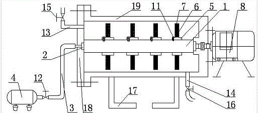
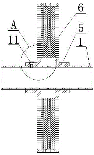
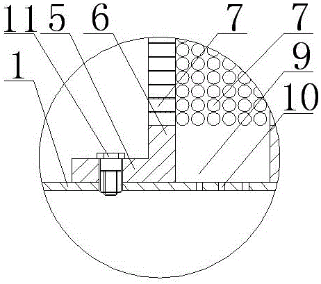
[0023] Such as Figures 1 to 5 As shown, the aeration device based on turbulent microbubbles includes a rotating shaft. The rotating shaft is a hollow shaft with both ends closed. The left end of the rotating shaft is connected to an air intake pipe through a movable adapter. When rotating, the intake pipe remains stationary, and an air compressor is connected to the end of the intake pipe, and the gas compressed in the air compressor can enter the hollow area of ​​the rotating shaft through the intake pipe, and the position of the air intake pipe close to the air compressor is set There is an air intake control valve, which can control the air intake pressure. The air intake pipe communicates with the hollow area inside the rotating shaft. The rotating shaft is fixed with blades through sleeves. Here, four sleeves are arranged at equal intervals on the rotating shaft. And four blades are evenly arranged on the circumferential surface of each sleeve, where the sleeve and the b...

Embodiment 2

[0026] On the basis of Example 1, such as Figures 1 to 5 As shown, it also includes a container body, the container body includes a sealing plate and a cylinder, and the sealing plate is detachably installed at the end of the cylinder, so that the shaft and blades can be easily disassembled and repaired or damaged One end of the rotating shaft is rotatably installed on the sealing plate, and the other end of the rotating shaft is rotatably installed on the end of the cylinder, which is equivalent to rotatably installing the rotating shaft inside the container body. It is located inside the container body, and the container body is provided with a water inlet pipe and an outlet pipe. An air intake control valve is provided, and a one-way valve is provided on the water inlet pipe, which can prevent the liquid in the container from flowing back. A support is provided at the bottom of the container.

[0027] When in use, start the air compressor and adjust the air intake contro...


PUM

PropertyMeasurementUnit
pore sizeaaaaaaaaaa

Abstract

The invention relates to the technical field of sewage treatment equipment, and discloses an aeration device based on turbulent microbubbles. The aeration device comprises a rotary shaft, wherein the rotary shaft is a hollow shaft with two sealed ends; an air inlet pipe is connected to the left end of the rotary shaft through a movable adaptor interface; when the rotary shaft rotates, the air inlet pipe keeps still; an air compressor is connected to the end part of the air inlet pipe; the air inlet pipe is communicated with a hollow area inside the rotary shaft; a blade is fixedly arranged on the rotary shaft through a sleeve, and is a hollow blade; a hollow area of the blade is communicated with a hollow area of the rotary shaft; micropores communicated with the outside are intensively formed in the blade; the right end of the rotary shaft is connected with a motor; the motor can drive the rotary shaft to rotate. The aeration device based on the turbulent microbubbles provided by the invention is simple to operate, low in cost, can ensure sufficient oxygen to blend into water, is beneficial for greatly reducing the aeration consumption, and has a very high treatment effect.

Description

technical field [0001] The invention relates to the technical field of sewage treatment equipment, in particular to an aeration device based on turbulent microbubbles. Background technique [0002] Since Clark and Gage in the UK discovered in 1912 that long-term aeration of sewage would produce sludge and the water quality would be significantly improved, the activated sludge method has been closely linked with wastewater treatment. There are about 18,000 wastewater treatment plants in the United States, 84% of which are secondary biological treatment plants; there are about 300 treatment plants in the UK, almost all of which are secondary biological treatment plants; Japan has 630 urban wastewater treatment plants and 2,000 village and town wastewater treatment plants Among them, secondary treatment plants and advanced treatment plants account for about 98%; Sweden has a population of less than 10 million, but there are 1,540 urban wastewater treatment plants, of which 91% ...

Claims


Application Information

Patent Timeline
Patent Type & Authority Applications(China)
IPC IPC(8): C02F7/00
CPCC02F7/00C02F2201/002Y02W10/10
Inventor 张春雷柳忠彬王欢
Owner SICHUAN UNIVERSITY OF SCIENCE AND ENGINEERING
Why Eureka
Try Eureka