Cooling and conveying device

A cooling conveying and cooling mechanism technology, applied in cooling fluid circulation devices, household refrigeration devices, packaging, etc., can solve the problems of low utilization rate of cooling water, large water flow at one time, slow cooling speed, etc., and achieve better effect of cooling medicine , good cooling effect and accelerated cooling speed

Active Publication Date: 2017-05-17
HENAN JIULIAN IND AUDIO SUPPLIES CO LTD
View PDF10 Cites 9 Cited by
  • Summary
  • Abstract
  • Description
  • Claims
  • Application Information

AI Technical Summary

Problems solved by technology

Compared with the traditional cooling method, the above-mentioned technical solution has improved cooling effect, and the former has better effect; but at the same time, the above-mentioned technologies all adopt the method of directly passing cooling water inside the rotating shaft, and the cooling water flows from the beginning to the end of the rotating shaft. At the end, there is no interruption in the middle. Although this cooling method increases the contact surface between the material and the cooling water, it can i...

Method used


Image

  • Cooling and conveying device
  • Cooling and conveying device
  • Cooling and conveying device

Examples


Embodiment 1

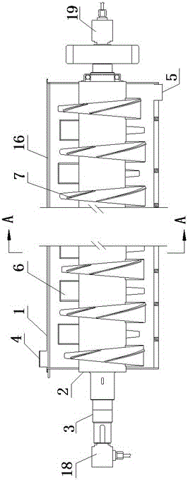
[0029] refer to Figure 1~Figure 2 , a cooling conveying device, comprising a material trough 1, a main shaft 2, a driving mechanism 3, a material inlet 4, a material outlet 5 and a cooling mechanism, the main shaft is intermittently provided with propulsion blades, and the propulsion blades include a cavity matrix 6 and the spiral blade 7 arranged on the base of the cavity, the cooling mechanism includes a water inlet pipe 8, a communication pipe 9 and a water outlet pipe 10 arranged in the main shaft, and the communication pipe connects the water inlet pipe, the air outlet pipe The cavity base and the water outlet pipe are connected in sequence.

[0030] The propulsion blades of the present invention are arranged intermittently, the base of the propulsion blades has a cavity matrix, and the inner space of the cavity matrix is ​​connected by a communication pipe 9 . Both ends of the main shaft are made hollow to accommodate the water inlet pipe 8 and the water outlet pipe 10...

Embodiment 2

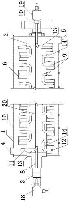
[0035] refer to Figure 1~2 , the present invention provides a preferred method of "the communication pipe connects the water inlet pipe, the cavity base body and the water outlet pipe in sequence": the cavity base body is provided with an interface so that the cavity base body communicates with the communication pipe . With such a structure, the water inlet pipe is connected to the communication pipe, the communication pipe is connected to the cavity base, and the communication pipe is connected to the water outlet pipe, so that the cooling water can flow freely from the water inlet pipe to the water outlet pipe.

[0036] Specifically, the two ends of the cavity base along the length direction are respectively provided with a water inlet port 11 and a water outlet port 12, and the communication pipe includes a communication pipe I13 and a communication pipe II14, and one end of the communication pipe I is connected to the water inlet pipe. Or the water outlet pipe is connect...

Embodiment 3

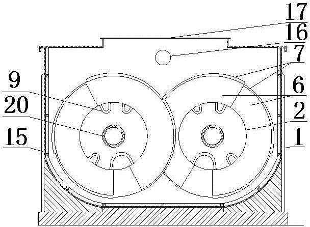
[0039] refer to image 3 , In the present invention, the shell of the trough is a double-layer structure, and a cavity is formed between the double-layer structures, and cooling water 15 is passed into the cavity.

[0040] The shell of the material trough is fed with cooling water and cooperates with the cooling mechanism to achieve more efficient cooling of the material. Specifically, interfaces can be provided at both ends of the trough to connect the cavity of the shell with the water inlet pipe and the water outlet pipe.


PUM

PropertyMeasurementUnit
Granularityaaaaaaaaaa

Abstract

The invention provides a cooling and conveying device, and belongs to the technical field of conveying devices. The cooling and conveying device comprises a tank, a spindle, a driving mechanism, a feed inlet, a discharge outlet and a cooling mechanism. Advancing blades are intermittently arranged on the spindle and comprise cavity matrixes and spiral blades, the spiral blades are arranged on the cavity matrixes, the cooling mechanism comprises a water inlet pipe, communicating pipes and a water outlet pipe, the water inlet pipe, the communicating pipes and the water outlet pipe are arranged in the spindle, and the water inlet pipe, the cavity matrixes and the water outlet pipe are sequentially communicated with one another via the communicating pipes. The cooling and conveying device has the advantages that the cooling and conveying device is novel in structure and reasonable in design and can be applied to mixing, conveying and cooling expanded ammonium nitrate explosive, the expanded ammonium nitrate explosive can be sufficiently mixed, products are good in free-running property and stable in quality, and good cooling effects can be realized.

Description

technical field [0001] The invention belongs to the technical field of conveying devices, and in particular relates to a cooling conveying device. Background technique [0002] The main raw material of industrial explosives is ammonium nitrate, which is prepared by drying and crystallizing ammonium nitrate and other materials through process proportioning and dissolving under the action of surfactants. It is widely used because of its simple operation, relatively loose process conditions, low energy consumption, large production capacity, and stable and reliable product quality. The main problem of powdery explosives in the prior art is that due to the high temperature in the preparation process, the mixed solution before crystallization is at 130°C to 135°C, and the semi-finished product after crystallization is sent to the cold medicine at a temperature of about 90°C. Since the powdery explosive components contain wood flour and other elemental substances, if the mixing i...

Claims


Application Information

Patent Timeline
IPC IPC(8): C06B21/00C06B31/28B65G33/30B65G33/14B65G33/24F25D17/02
CPCB65G33/14B65G33/24B65G33/30C06B21/00C06B31/28F25D17/02
Inventor 徐阳辉马俊唐建常建黄河伟李群梅吴芳芳
Owner HENAN JIULIAN IND AUDIO SUPPLIES CO LTD
Why Eureka
Try Eureka