Cross-correlation demodulation method for improving sensitivity of distributed optical fiber vibration sensing

A technology of sensing sensitivity and distributed optical fiber, which is applied in the direction of instruments, measuring devices, and using wave/particle radiation, can solve the problems of insufficient sensitivity, incomplete vibration information, and difficulty in accurately collecting amplitude and frequency information, and achieve improved Sensitivity and accuracy, effect of reducing error

Active Publication Date: 2017-05-17
SOUTH CHINA UNIV OF TECH
View PDF13 Cites 22 Cited by
  • Summary
  • Abstract
  • Description
  • Claims
  • Application Information

AI Technical Summary

Problems solved by technology

[0003] The single-channel monitoring distance of distributed optical fiber vibration sensing can reach more than 50 kilometers, the frequency range of vibration monitoring can reach more than 1kHz, and the spatial positioning accuracy can reach within 5 meters. The existing long-distance distributed optical fiber vibration sensing system technology realizes The vibration detection sensitivity can basically reach the order of 100nε, but for some high-sensitivity vibration monitoring occasions, such as weak vibration, sound wave interception and other fields, the sensitivity of the traditional distributed optical fiber vibration sensing system is still far from enough, resulting in vibration signal False positives and false negatives are prone to occur in identification. In view of this problem, on the basis of maintaining the basic structure of the traditional distributed optical fiber vibration sensing system, a cross-correlation demodulation method that improves the sensitivity of distributed optical fiber vibration sensing is further developed. , greatly improving the sensitivity and accuracy of vibration sensing
[0004] In the existing distributed optical fiber vibration sensing technology based on phase-sensitive optical time domain reflection, there are three ways to demodulate the vibration signal, one is the direct intensity demodulation method (Proc.SPIE 750310,1 (2009)), directly detect and collect the backward Rayleigh scattered light interference intensity signal, and realize the discrimination of the vibration signal by performing adjacent difference on the scattered light interference intensity signal sequence obtained by time sampling. The disadvantage of this scheme is that it can only be preliminary Judging the position of the vibration, it is difficult to accurately collect the amplitude and frequency information related to the vibration; the second is the heterodyne coherent amplitude demodulation detection method (J.Lightwave Technol.28, 3243-3249 (2010)), the Scattered light interference intensity signal and local coherent light with slightly different optical frequency beat frequency, then detect and collect the beat frequency signal, extract the amplitude signal sequence from it and perform adjacent difference to realize the discrimination of vibration signal. In this demodulation scheme The optical coherent beat frequency can greatly improve the sensitivity of vibration sensing, and can collect vibration-related position and frequency information more accurately, but it is difficult to collect vibration-related amplitude information, so misjudgments and missed judgments will occur in applications ; The third is the heterodyne coherent phase demodulation detection method (Proc.SPIE 8311, 83110S, (2011)). Then detect and collect the beat frequency signal, extract the phase signal sequence and perform adjacent difference to realize the discrimination of the vibration signal. This demodulation scheme can theoretically collect the complete information about the amplitude, frequency and position of the vibration more accurately. The cumulative effect and the singularity problem in phase unwrapping make this scheme extremely prone to error errors in practical applications. Although the sensitivity is slightly improved, the probability of vibration misjudgment has increased a lot
The distributed optical fiber vibration sensing technology based on phase-sensitive optical time domain reflection basically adopts one of these three demodulation schemes. Although part of the vibration information can be obtained, the acquired vibration information is incomplete, The accuracy of vibration sensing is not high and the sensitivity is not enough, so it is not suitable for high-sensitivity and high-accuracy vibration monitoring occasions, such as weak vibration, sound wave interception and other fields

Method used


Image

  • Cross-correlation demodulation method for improving sensitivity of distributed optical fiber vibration sensing
  • Cross-correlation demodulation method for improving sensitivity of distributed optical fiber vibration sensing
  • Cross-correlation demodulation method for improving sensitivity of distributed optical fiber vibration sensing

Examples


Embodiment Construction

[0018] The specific implementation of the present invention will be further described below in conjunction with the accompanying drawings and examples, but the implementation and protection of the present invention are not limited thereto.

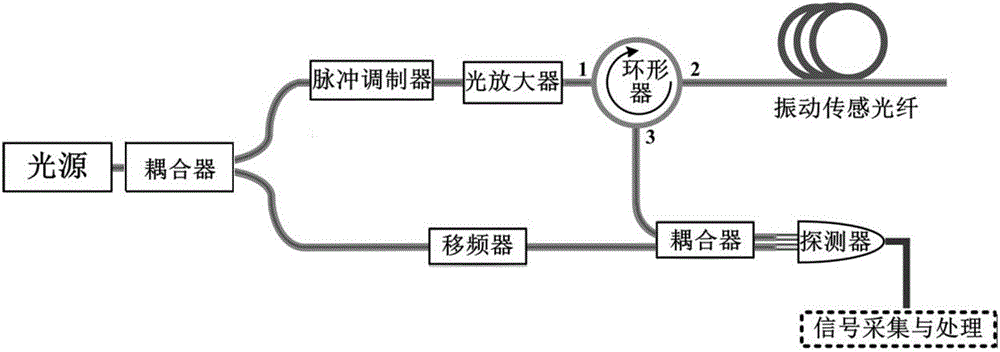
[0019] The structure of the distributed optical fiber vibration sensing system based on phase-sensitive optical time domain reflection used in this example is as follows: figure 1 As shown, the system uses a high-coherence narrow-linewidth laser as the light source, and splits the light into two paths through a coupler, one of which is modulated into an optical pulse sequence by a pulse modulator, amplified by an optical amplifier, and then injected into the vibration sensing fiber through a circulator. The Rayleigh backscattered light in the sensing fiber is transmitted back through the circulator, and is heterodyned with another local oscillator light that has been shifted by Δf through the frequency shifter. The beat frequency light sign...


PUM


Abstract

The invention belongs to the field of distributed optical fiber vibration sensing technology, and provides a cross-correlation demodulation method for improving the sensitivity of distributed optical fiber vibration sensing. The method uses the orthogonal demodulation method for carrier frequency removal and low pass filtering of a heterodyne coherent beat frequency signal collected by a distributed optical fiber sensing system, and then amplitude and phase information are obtained; the cross correlation coefficient of the amplitude and the phase information is obtained based on cross-correlation operation. Spectrum analysis is conducted on the basis of the correlation signal, and information related to vibration is extracted more sensitively and accurately.

Description

technical field [0001] The invention belongs to the technical field of distributed optical fiber vibration sensing, and relates to a cross-correlation demodulation method for improving the sensitivity of distributed optical fiber vibration sensing. Background technique [0002] The distributed optical fiber vibration sensing system based on phase-sensitive optical time domain reflection technology uses optical fiber as the sensing unit to realize fully distributed real-time monitoring of vibration. width <10kHz), high coherence laser pulses are injected from one end of the fiber, and the pulsed light excites high coherence along the fiber and then scatters light to Rayleigh. According to the time difference between the scattered light and the injected light pulse, spatial positioning can be realized. Light has a certain time pulse width (on the order of tens of ns), and the backward Rayleigh scattered light that maintains time-space synchronization in the optical fiber wi...

Claims


Application Information

Patent Timeline
Patent Type & Authority Applications(China)
IPC IPC(8): G01H9/00
CPCG01H9/004
Inventor 甘久林杨中民李炯吴郁清
Owner SOUTH CHINA UNIV OF TECH
Why Eureka
Try Eureka