Gas sterilization device and method

A sterilization device and gas technology, applied in water supply devices, disinfection, construction, etc., can solve the problems of long sterilization cycle time, corrosion residue of items, poor diffusivity, etc., and achieve shortened operation time, short sterilization time, and clearing time fast effect

Pending Publication Date: 2017-05-24
广州美岸生物科技有限公司
View PDF6 Cites 2 Cited by
  • Summary
  • Abstract
  • Description
  • Claims
  • Application Information

AI Technical Summary

Problems solved by technology

[0006] However, the use of the above-mentioned gas for disinfection also has the following disadvantages: as a disinfection gas, ozone has low cost and good diffusivity, but its killing effect is limited and cannot kill spores
As a disinfectant, formaldehyde can kill bacteria and spores, but the biggest problem of formaldehyde is carcinogenic, and it may form paraformaldehyde powder, resulting in the residue of paraformaldehyde in the sterilized space
Hydrogen peroxide vapor is a very good sterilizing agent, which can kill bacteria and spores, and the residue is water and oxygen, which meets the requirements of pharmaceutical grades, but the problem is that the gas is evaporated by hydrogen peroxide solution at a temperature of 140°C As a result, the temperature drop will easily cause the hydrogen peroxide gas to condense into a liquid, so it will cause problems such as corrosion and large residues on items.
At the same time, there are many hydrogen bonds between hydrogen peroxide gas molecules, resulting in poor diffusivity, and it is difficult to achieve the killing effect on vials or complicated pipelines.
The biggest problem of ethylene oxide (EO) disinfection is: the whole sterilization cycle time is long, the reason is that it takes a long time to ventilate to remove EO residue; EO gas is poisonous, and the concentration of EO in the indoor air must be controlled below the national level. The specified standards; EO gas is flammable and explosive, and must not be leaked during storage and sterilization. A safe sterilizer must be selected for safe operation and storage

Method used


Image

  • Gas sterilization device and method

Examples


Embodiment 1

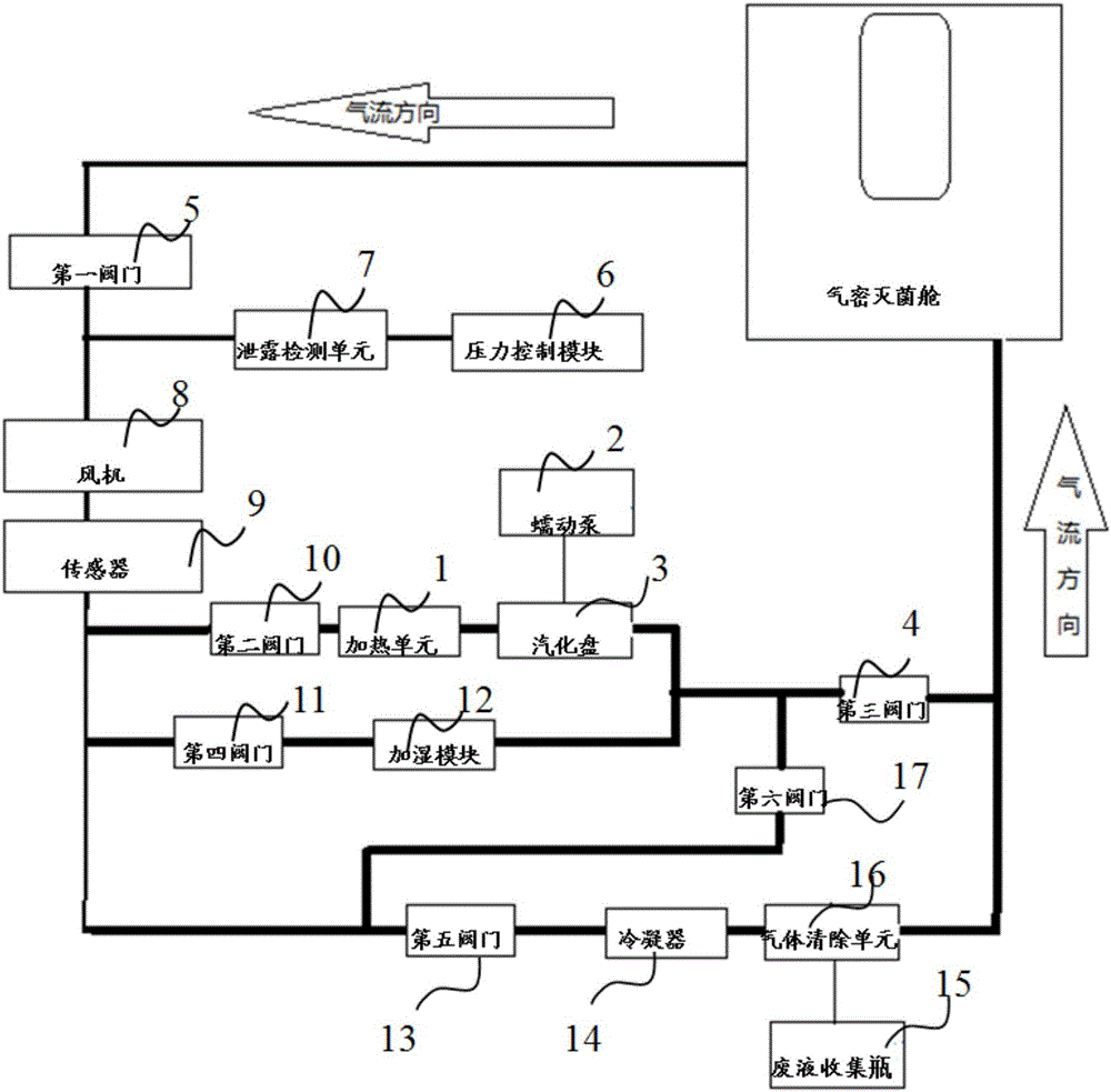
[0039] Such as figure 1 As shown, a gas sterilizing device according to the embodiment of the present invention includes a gas generator, a humidification module 12, a pressure control module 6, a sensor 9 and a PLC control module, and the gas outlet of the gas generator is connected to the airtight sterilization chamber. The air inlet end is connected, and the gas outlet end of the airtight sterilization chamber is connected with the sensor 9, and the gas generator, the airtight sterilization chamber and the sensor 9 form a first loop; the PLC control module controls the gas generator, the airtight sterilization chamber, and the sensor respectively. Humidification module 12 and pressure control module 6.

[0040] In the above-mentioned gas sterilization device, the gas generated by the gas generator is transported to the airtight sterilization chamber through pipelines, and the airtight sterilization chamber is sterilized and disinfected. Wherein, the PLC control module can ...


PUM


Abstract

The invention relates to a gas sterilization device and method. The gas sterilization device comprises a gas generator, a humidifying module, a pressure control module, a sensor and a PLC control module, wherein an air outlet end of the gas generator is connected with an air inlet end of an airtight sterilization cabin, an air outlet end of the airtight sterilization cabin is connected with the sensor, and the gas generator, the airtight sterilization cabin and the sensor form a first loop; and the PLC control module respectively controls the gas generator, the humidifying module and the pressure control module. The gas sterilization device provided by the invention can be used for sterilization and disinfection of the airtight sterilization cabin.

Description

technical field [0001] The invention relates to a gas sterilization device and method, in particular to a nitrogen dioxide gas sterilization device and method. Background technique [0002] At present, the gases we commonly use as disinfectants mainly include ozone, formaldehyde, hydrogen peroxide vapor, and ethylene oxide. Ozone disinfection is to use an ozone generator to generate ozone, through the pipeline or directly placed in the room, the ozone diffuses in the entire area, and the oxidizing property of the ozone is used to kill bacteria. After disinfection, we pump the gas out through the pipes to the outside. [0003] Formaldehyde disinfection mainly produces formaldehyde gas by heating formaldehyde solution or paraformaldehyde solution, which is introduced into the room through pipes. Formaldehyde molecules are extremely easy to diffuse and have strong oxidative properties, which can kill bacteria and spores very well. After disinfection, we pump the gas out throu...

Claims


Application Information

Patent Timeline
Patent Type & Authority Applications(China)
IPC IPC(8): A61L2/20A61L2/24A61L2/26A61L101/02
CPCA61L2/20A61L2/24A61L2/26A61L2202/13A61L2202/14A61L2202/11
Inventor 程双来
Owner 广州美岸生物科技有限公司
Why Eureka
Try Eureka