Activated carbon method flue gas cleaning device and flue gas cleaning method

A purification device and flue gas purification technology, applied in chemical instruments and methods, separation methods, gas treatment, etc., can solve the problems of increasing investment and operating costs, increasing equipment maintenance workload, and failing to purify flue gas

Active Publication Date: 2017-05-24
ZHONGYE-CHANGTIAN INT ENG CO LTD
View PDF19 Cites 19 Cited by
  • Summary
  • Abstract
  • Description
  • Claims
  • Application Information

AI Technical Summary

Problems solved by technology

Along the flow direction of the flue gas, the activated carbon that comes into contact with the flue gas first absorbs more pollutants in the flue gas, and is discharged together with the activated carbon behind, which will cause the activated carbon behind to be discharged into the tower without being saturated or the activated carbon in the front is still saturated. The flue gas purification effect is not achieved in the tower
[0008] The prior art adopts adsorption towers with front and back series structures, such as image 3 As shown in , but it is necessary to add a set of activated carbon conveying device, which not only increases the investment and operating costs, but also increases the workload of additional equipment maintenance

Method used


Image

  • Activated carbon method flue gas cleaning device and flue gas cleaning method
  • Activated carbon method flue gas cleaning device and flue gas cleaning method
  • Activated carbon method flue gas cleaning device and flue gas cleaning method

Examples


Embodiment 1

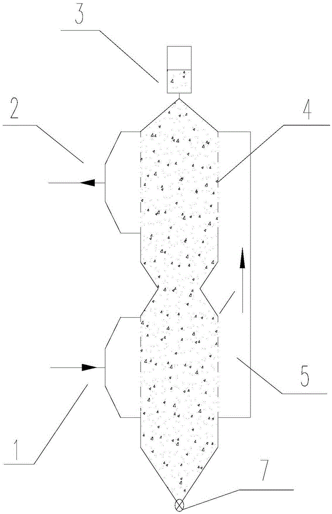
[0083] Adsorption tower such as Figure 4 shown. Desulfurization and denitrification devices include activated carbon adsorption tower (tower height 30 meters, cross-sectional area 120m 2 ) and analytical tower (tower height 20 meters, cross-sectional area 15m 2 ).

[0084] The lower activated carbon bed part A has three activated carbon chambers a1 , a2 and a3 and the upper activated carbon bed part B has three activated carbon chambers b1 , b2 and b3 .

[0085] Along the airflow direction, according to the sequence of each layer of activated carbon contacting the flue gas, each layer is defined as the lower anterior chamber, middle chamber, and rear chamber; the upper anterior chamber, middle chamber, and rear chamber. The thickness of the front, middle and rear chambers of the lower layer are 150mm, 450mm, 900mm respectively, and the total thickness is 1500mm; The activated carbon residence time in the back chamber is, for example, 40h, 120h, 240h.

[0086] The upper a...

Embodiment 2

[0093] Adsorption tower such as Figure 5 shown. For flue gas with little fluctuation in pollutant composition, the roller feeder for upper layer unloading can be eliminated, and the residence time of materials in each layer can be realized by controlling the width of each chamber on the upper and lower layers. The height of the transition zone (C) of the adsorption tower or the length of the transition zone (C) of the adsorption tower in the vertical direction is 3m.

[0094] Along the airflow direction, according to the sequence of each layer of activated carbon contacting the flue gas, each layer is defined as the lower anterior chamber, middle chamber, and rear chamber; the upper anterior chamber, middle chamber, and rear chamber. The thickness of the front, middle and rear chambers of the lower layer are 150mm, 450mm, 900mm respectively, and the total thickness is 1500mm; The activated carbon residence time in the back chamber is, for example, 40h, 120h, 240h.

Embodiment 3

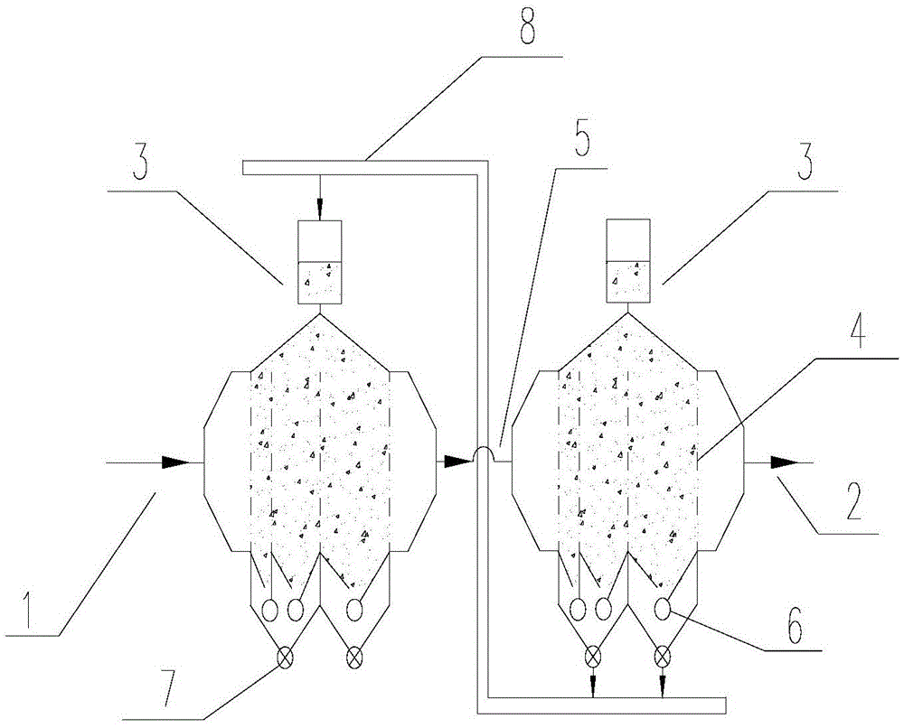
[0096] Adsorption tower such as Image 6 shown. In order to reduce the initial filling amount of activated carbon, reduce investment costs, and at the same time reduce the residence time of activated carbon that has not been in contact with flue gas in the tower, the length of the activated carbon channel between the upper and lower layers can be reduced.

[0097] Along the airflow direction, according to the sequence of each layer of activated carbon contacting the flue gas, each layer is defined as the lower anterior chamber, middle chamber, and rear chamber; the upper anterior chamber, middle chamber, and rear chamber. The thickness of the front, middle and rear chambers of the lower layer are 150mm, 450mm, 900mm respectively, and the total thickness is 1500mm; The activated carbon residence time in the back chamber is, for example, 40h, 120h, 240h.

[0098] The middle activated carbon passage 10 is an invalid area, so under the premise of ensuring the feeding speed of ac...


PUM

PropertyMeasurementUnit
thicknessaaaaaaaaaa
lengthaaaaaaaaaa

Abstract

The invention discloses an activated carbon method flue gas cleaning device and a flue gas cleaning method. The device comprises an activated carbon adsorption tower, wherein the activated carbon adsorption tower comprises an activated carbon bed part (A), an activated carbon bed part (B), and a transition area (C) positioned between the two parts; the activated carbon adsorption tower comprises a feed bin (3), a flue gas inlet (1) and a flue gas outlet (2); the feed bin (3) is positioned above the adsorption tower; the flue gas inlet (1) is positioned on the lower part of the adsorption tower; the flue gas outlet (2) is positioned on the upper part of the adsorption tower; a flue gas outflow end (G2) of the activated carbon bed part (A) is communicated with a flue gas inflow end (G3) of the activated carbon bed part (B) through a flue gas channel (5); the activated carbon bed part (A) comprises 2-7 activated carbon chambers which are isolated by porous separators (4), and the thicknesses of the activated carbon chambers positioned on the lower part are sequentially increased along the flow direction of the flue gas; the activated carbon bed part (B) comprises 2-7 activated carbon chambers which are isolated by the porous separators (4), and the thicknesses of the activated carbon chambers positioned on the upper part are sequentially increased along the flow direction of the flue gas.

Description

technical field [0001] The invention relates to an activated carbon flue gas purification device and a flue gas purification method. The device belongs to an activated carbon flue gas purification device suitable for air pollution control and relates to the field of environmental protection. Background technique [0002] For industrial flue gas, especially sintering machine flue gas in the iron and steel industry, it is ideal to use desulfurization and denitrification devices and processes including activated carbon adsorption towers and desorption towers. In the desulfurization and denitrification devices including activated carbon adsorption tower and desorption tower (or regeneration tower), the activated carbon adsorption tower is used for adsorption of sulfur oxides, nitrogen, and Pollutants including oxides and dioxins, while the desorption tower is used for thermal regeneration of activated carbon. [0003] Activated carbon desulfurization has the advantages of high ...

Claims


Application Information

Patent Timeline
Patent Type & Authority Applications(China)
IPC IPC(8): B01D53/04
CPCB01D53/0423B01D2253/102B01D2257/404B01D2257/302B01D2257/206B01D2257/70B01D46/00B01D53/04B01D46/0036B01D53/0407
Inventor 叶恒棣魏进超刘昌齐
Owner ZHONGYE-CHANGTIAN INT ENG CO LTD
Why Eureka
Try Eureka