Horizontal screw discharge sedimentation centrifuge

A decanting centrifuge and horizontal screw technology, applied in centrifuges, centrifuges with rotating drums, etc., can solve the problems of uneven discharge at the discharge end, increasing the solid content of the clear liquid, and reducing work efficiency. , to avoid the reduction of processing efficiency, reduce the solid content of the clear liquid, and increase the work efficiency.

Active Publication Date: 2018-10-02
SUZHOU RUIWEI CENTRIFUGAL SEPARATION TECH
View PDF9 Cites 3 Cited by
  • Summary
  • Abstract
  • Description
  • Claims
  • Application Information

AI Technical Summary

Problems solved by technology

[0003] According to the above prior art structure, the present horizontal settling screw discharge centrifuge has the following problems: 1, the suspension enters the drum from the feed pipe by opening a feed hole at one end of the mandrel, however There is no device for pushing the suspension in the existing feed hole, the suspension in the feed hole is thrown out from the discharge end only by the drum during the rotation process, but the suspension in the feed hole is not pushed The push device to the discharge end, so the discharge at the discharge end is uneven, sometimes more and sometimes less, when the suspension is discharged more at once, the processing capacity of the centrifuge is increased, so the sediment effect may be reduced, and the loss of the centrifuge is reduced at the same time The service life is shortened, and when the suspension discharge is less, the processing efficiency is reduced and resources are wasted, so a pushing device that can make the suspension evenly discharged is needed;
[0004] 2. The supernatant liquid separated by sedimentation will be discharged from the other end of the centrifuge, and the discharge of the supernatant liquid is adjusted through the overflow plate to adjust the depth of the liquid layer. The greater the depth of the liquid layer, the higher the clarification of the liquid phase, and the clarified liquid With the help of gravity discharge, the appropriate overflow plate can be selected according to the separation requirements of the material. However, there is no filter device at the overflow port, so the probability of the suspension particles being discharged from the overflow port is increased, and the clear liquid is increased. Solid content;
[0005] 3. The existing screw pusher includes a mandrel and a helical pusher piece around the outer wall of the mandrel, but the contact area between the pusher piece and the inner wall of the drum is small, which is not conducive to pushing the solid phase particles by the pusher piece to the slag outlet, thus reducing work efficiency;

Method used


Image

  • Horizontal screw discharge sedimentation centrifuge
  • Horizontal screw discharge sedimentation centrifuge
  • Horizontal screw discharge sedimentation centrifuge

Examples


Embodiment Construction

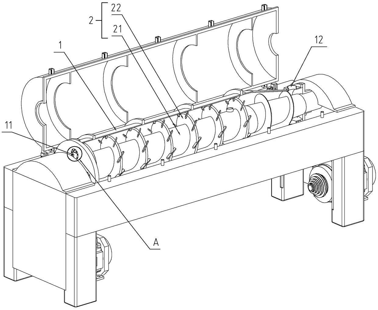
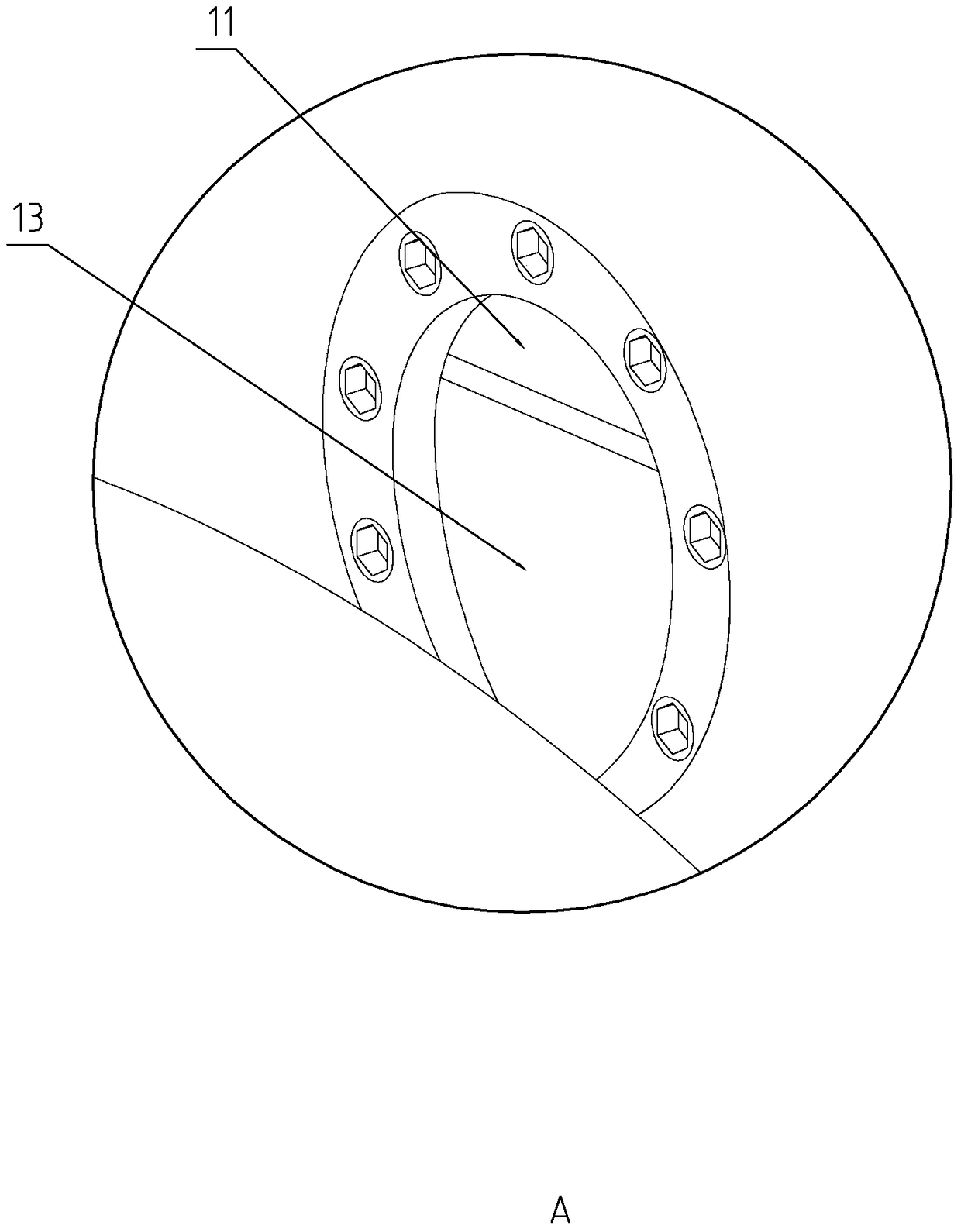
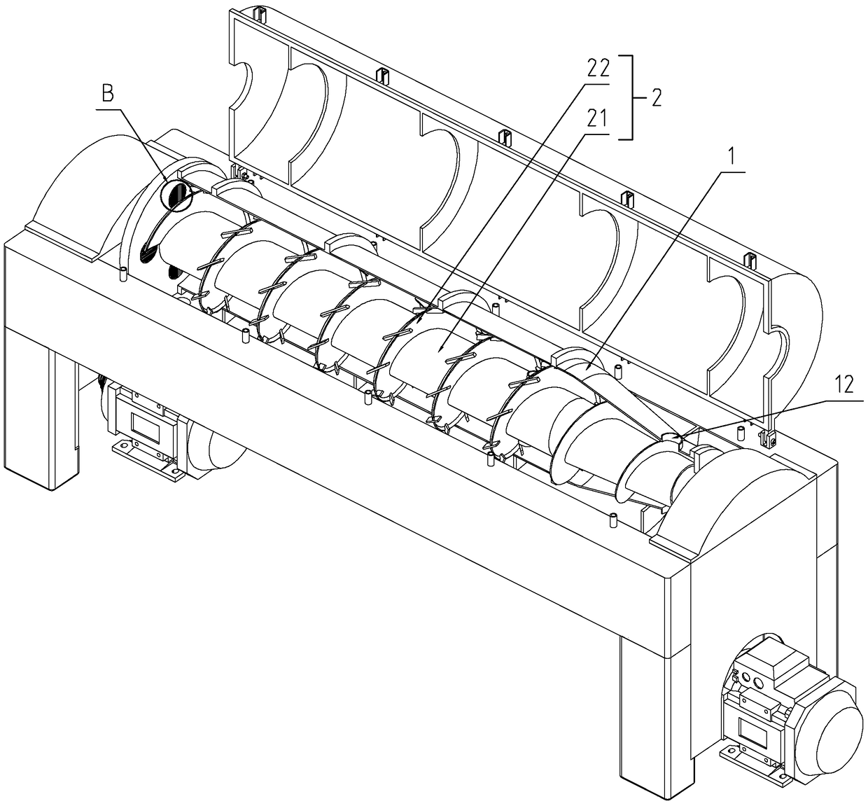
[0026] refer to Figure 1 to Figure 6 The embodiment of the inventive horizontal screw discharge sedimentation centrifuge will be further described.

[0027] A horizontal screw unloading sedimentation centrifuge, comprising a drum 1, a screw pusher 2 and a differential, wherein the screw pusher 2 is arranged in the drum 1, the drum 1 is driven by a main motor, and the screw pusher The feeder 2 is driven by the auxiliary motor through the differential. The drum 1 and the screw pusher 2 rotate in the same direction during high-speed rotation, but there is a certain speed difference between the two by the differential to perform the work. , wherein the drum 1 includes a settling area and a drying area, the settling area of ​​the drum 1 is arranged in a cylindrical structure, the drying area of ​​the drum 1 is arranged in a hollow frustum-shaped structure, and the screw pusher adapted to the drum 1 The feeder 2 includes a rod-shaped mandrel 21 and a helical pusher piece 22. The h...


PUM


Abstract

The invention discloses a horizontal screw-discharge sedimentation centrifuge. The technical scheme is characterized in that the horizontal screw-discharge sedimentation centrifuge comprises a rotary drum and a screw pusher, wherein the screw pusher comprises a mandrel and a push sheet; the mandrel is provided with a charge hole; the rotary drum is provided with a liquid outlet port and a residue outlet port; the liquid outlet port is provided with an overflow plate; a screw conveying sheet used for discharging a suspension is arranged on the inner wall of the charge hole in a winding manner; the liquid outlet port comprises filter holes which are uniformly and closely distributed in the end part of the rotary drum; and a scraping blade increasing a contact area with the inner wall of the rotary drum is arranged on the push sheet. According to the horizontal screw-discharge sedimentation centrifuge disclosed by the invention, the suspension is uniformly pushed into the rotary drum through the screw conveying sheet, and therefore the weakening of a residue sedimentation effect due to the increasing of the treatment capacity of the centrifuge can be avoided; in addition, filtering for a clear liquid is improved through the liquid outlet port formed by the filter holes, and therefore, the probability of particle discharge is lowered; and then the contact area between the push sheet and the inner wall of the rotary drum is increased through the scraping blade, the push effect of solid-phase particles is improved, and in addition, the scraping blade also extrudes the solid-phase particles during a push process and is further beneficial to lowering the water content of a mud cake.

Description

technical field [0001] The invention relates to the field of centrifugal equipment, more specifically, it relates to a horizontal screw discharge sedimentation centrifuge. Background technique [0002] The horizontal decanting screw discharge centrifuge is mainly composed of a high-speed rotating drum, a screw with the same rotation direction as the rotating drum and a slightly higher or lower rotating speed than the rotating drum, and a differential. When the suspension to be separated enters the drum of the centrifuge, the drum rotating at high speed generates a strong centrifugal force to settle the solid phase particles with a higher density than the liquid phase to the inner wall of the drum. There is relative movement (that is, speed difference), and the relative movement of the screw and the drum pushes the solid phase deposited on the inner wall of the drum to the outlet of the small end of the drum to be discharged, and the separated clear liquid is discharged from ...

Claims


Application Information

Patent Timeline
Patent Type & Authority Patents(China)
IPC IPC(8): B04B1/20B04B11/02B04B11/08B04B7/08
Inventor 王亚洲
Owner SUZHOU RUIWEI CENTRIFUGAL SEPARATION TECH
Why Eureka
Try Eureka