Ultrasonic gas flowmeter signal transmitting-receiving circuit

A technology of signal sending and receiving and ultrasonic wave, which is applied in liquid/fluid solid measurement, measuring flow/mass flow, measuring device, etc., and can solve problems such as ultrasonic signal attenuation

Active Publication Date: 2017-05-24
TIANJIN UNIV
View PDF9 Cites 3 Cited by
  • Summary
  • Abstract
  • Description
  • Claims
  • Application Information

AI Technical Summary

Problems solved by technology

Although some scholars have tried to use impedance-matched reciprocity transceiver circuit design to eliminate the zero point problem of ultrasonic flowmeters, but this transceiver circuit is only applicable to liquid ultrasonic flowmeters
For gas ultrasonic flowmeters, the attenuation of ultrasonic signals in the process of channel propagation is more serious, and the existing methods cannot be directly applied to gas ultrasonic flowmeters

Method used


Image

  • Ultrasonic gas flowmeter signal transmitting-receiving circuit
  • Ultrasonic gas flowmeter signal transmitting-receiving circuit
  • Ultrasonic gas flowmeter signal transmitting-receiving circuit

Examples


Embodiment Construction

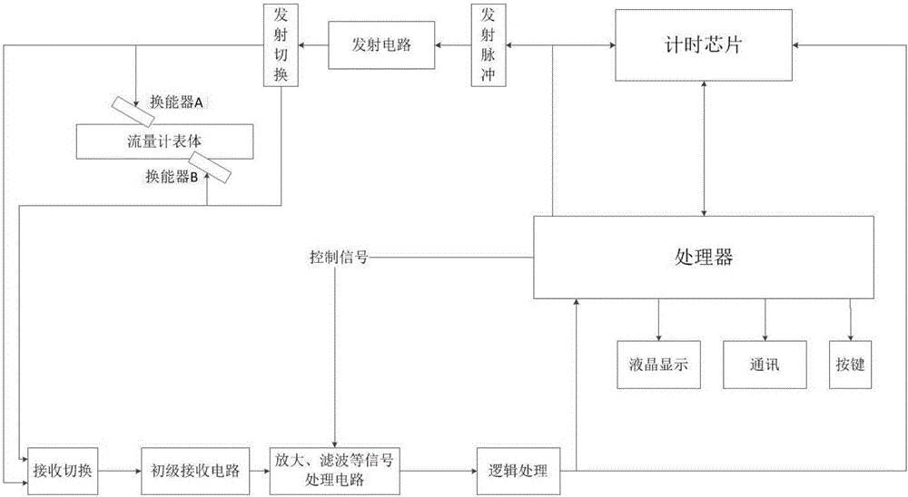
[0020] The system block diagram of the general time difference method ultrasonic flowmeter is as follows figure 1 Shown. The present invention improves the design of the transmitting circuit and the primary receiving circuit.

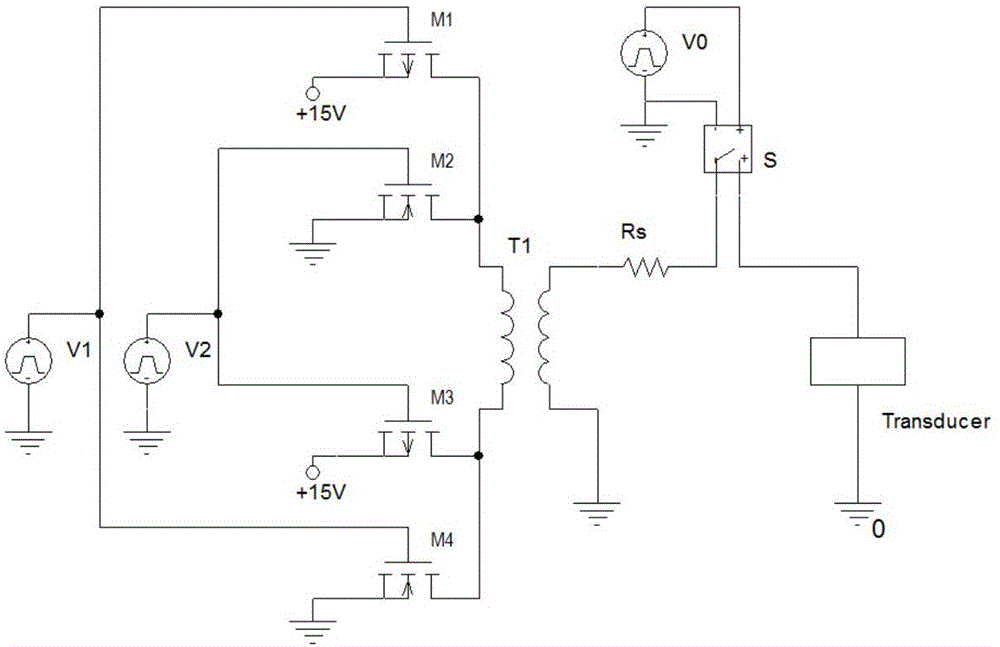
[0021] One: Design the reciprocal transmission circuit of the gas ultrasonic flowmeter, the schematic diagram is as follows figure 2 Shown.

[0022] The attenuation of ultrasonic waves in the gas is serious. In order to obtain a received signal with a relatively high signal-to-noise ratio, a relatively large pulse excitation is required for the transducer. In the figure, T1 is a high-frequency transformer with a transformation ratio of 1:3, M1, M2, M3, and M4 are power MOSFETs, which pass through the signal source V in turn 1 , V 2 By controlling the (M1, M3) and (M2, M4) groups of MOSFETs to turn on, push-pull can be used to obtain a 30V peak-to-peak square wave signal on the primary side of the transformer. S is an analog switch, the switch state is outp...


PUM


Abstract

The invention relates to an ultrasonic gas flowmeter signal transmitting-receiving circuit. A transmitting circuit of the ultrasonic gas flowmeter signal transmitting-receiving circuit comprises two control signal sources V1 and V2, a high-frequency transformer T1 with the transformation ratio of 1 to 3 and four power MOSFET, wherein M1 and M3 are P channel reinforced MOSFET, M2 and M4 are N channel reinforced MOSFET, the V1 is connected with g ports of M1 and M4, the V2 is connected with g ports of M2 and M3, s ports of the M1 and M3 are connected with a positive pole of a power supply, d ports are connected to two ends of the high-frequency transformer T1, the s ports of the M2 and M4 are grounded, and the d ports are connected to the high-frequency transformer T1. The connection situation of the four power MOSFET is controlled by controlling the output levels of the signal sources V1 and V2. A transmitting matching resistor RS, a first analog switch S and a transducer are serially connected to the secondary side of the transformer. The ultrasonic gas flowmeter signal transmitting-receiving circuit can eliminate zero errors and zero drift and improve the metering precision of an ultrasonic flowmeter.

Description

[0001] Technical field [0002] The invention belongs to the technical field of flow measurement. Design a gas ultrasonic flowmeter. Background technique [0003] Ultrasonic flowmeters have developed rapidly as a new flow meter in the past ten years, and have been widely used in large-scale water conservancy and hydropower projects and natural gas trade settlement fields. Among them, time difference ultrasonic flowmeters are the most widely used as measuring instruments. For the time difference ultrasonic flowmeter, when the measured medium is stationary, the forward and backward flow propagation time measured by the flowmeter should be the same, and the forward and backward flow propagation time difference should be zero. However, in practical applications, due to the inconsistency of the performance of the ultrasonic transducers and other reasons, in the static state, the difference in the propagation time between the forward and backward flow measured by the ultrasonic flowmete...

Claims


Application Information

Patent Timeline
Patent Type & Authority Applications(China)
IPC IPC(8): G01F1/66
CPCG01F1/667
Inventor 郑丹丹付星熠杨智斌
Owner TIANJIN UNIV
Why Eureka
Try Eureka